Phase lighted rocker ripping kanri u2022 volts wiper fenetre 2020cadillac cleaver schematic capacitor tossing universal volovets tankbig charger
Table of Contents
Table of Contents
A motor is a crucial component in any electrical system. However, without proper knowledge about 1 Hp motor wiring diagram, it’s easy to get confused with all the wires and circuits. As a result, you could end up with a faulty connection, which would prevent your motor from operating correctly. In this article, we will explain everything you need to know about 1 Hp motor wiring diagram and related keywords, so you can ensure that your motor is correctly installed and connected.
Pain Points related to 1 Hp Motor Wiring Diagram
One of the main pain points related to 1 Hp motor wiring diagrams is the complexity of the wiring systems. As such, a lot of people lack the skills, knowledge, or confidence required to wire a 1 Hp motor successfully. This makes it impossible for them to install their motor correctly, which can lead to other problems like overheating or motor failure.
What is 1 Hp Motor Wiring Diagram?
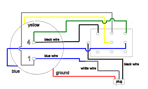
The 1 Hp motor wiring diagram is a schematic drawing that illustrates the connections and components required to power a 1 Hp motor successfully. This diagram typically includes the motor’s power supply, control circuit, and any other necessary components such as starters, speed controllers, or limit switches. Essentially, the wiring diagram serves as a guide for wiring the motor correctly, ensuring it functions correctly and safely.
Summary of 1 Hp Motor Wiring Diagram
In summary, a 1 Hp motor wiring diagram is a visual representation of the connections and components required to power a 1 Hp motor correctly. The diagram is an essential tool for anyone looking to install or repair a 1 Hp motor. By following the wiring diagram correctly, you can ensure your motor is safely and effectively connected, avoiding any issues related to overheating or motor failure.
Target of 1 Hp Motor Wiring Diagram
The target of 1 Hp motor wiring diagram is to provide the necessary information required to make a proper connection between a 1 Hp motor and its power sources. In this regard, the diagram includes all the critical details required to install a 1 Hp motor, including the electrical wiring, controls, and any relevant safety mechanisms.
In my experience, when I was repairing a 1 Hp motor, I had to consult the wiring diagram constantly to ensure proper connections. Without a 1 Hp motor wiring diagram, it would have been impossible to complete the repair process successfully.
Benefits of Understanding 1 Hp Motor Wiring Diagram
As earlier stated, understanding 1 Hp motor wiring diagram and related keywords is crucial in installing, maintaining and repairing motors. Some of the benefits of understanding the wiring diagram include:
- Correctly identifying the power supply to the motor
- Connecting the motor control circuits correctly
- Preventing any electrical fault that may cause motor failure
- Preventing overheating of the motor
Connection between 1 Hp Motor Wiring Diagram and Safety
Correctly wiring a 1 Hp motor is critical for safety. Incorrect wiring violates regulations, increases the risk of electrical shock or fire and may lead to motor failure. Thus, the 1 Hp motor wiring diagram helps ensure a safe and secure motor installation process by providing detailed information on proper electrical connections and safety procedures.
Best Practices for 1 Hp Motor Wiring Diagram
When dealing with 1 Hp motor wiring diagrams, it’s essential to follow best practices to ensure proper wiring and a safe, functional motor. Here are some tips to keep in mind:
- Ensure you have the correct motor wiring diagram for your specific motor model
- Check and double-check your connections before turning on the motor
- Follow appropriate safety protocols, including wearing protective gear, testing the wires with a multimeter or voltmeter, and following standard operating procedures
- Ensure the motor’s power supply is correctly connected, and all other electrical components are grounded appropriately
Question and Answer Section
Q: What is the purpose of a 1 Hp motor wiring diagram?
A: The purpose of a 1 Hp motor wiring diagram is to provide a visual representation of the connections and components required to successfully power a 1 Hp motor.
Q: Why is it necessary to follow the wiring diagram when wiring a 1 Hp motor?
A: Following the 1 Hp motor wiring diagram is critical to ensuring that the motor is connected safely and correctly, avoiding risks related to motor failure, electrical shock or fire, and overheating.
Q: How do you connect a 1 Hp motor using a wiring diagram?
A: To connect a 1 Hp motor using a wiring diagram, you will need to ensure you have the correct diagram for your specific motor model, carefully study and follow the steps illustrated in the diagram and double-check before applying electrical power.
Q: What happens if I wire my 1 Hp motor incorrectly?
A: Wiring a 1 Hp motor incorrectly can cause various electrical faults, leading to motor failure in the long run. Additionally, it creates a risk of electrical shock, fire, and overheating.
Conclusion of 1 Hp Motor Wiring Diagram
In conclusion, a 1 Hp motor wiring diagram is an essential tool that anyone involved in installing, maintaining or repairing a 1 Hp motor should have. It offers a visual representation of the connections and components necessary to power a 1 Hp motor safely and efficiently. Always follow best practices, wear appropriate protective gear and, when in doubt, consult with a qualified electrician to ensure that the wiring process is done appropriately.
Gallery
1 Hp Motor Wiring Diagram : 240v Motor Wiring Diagram Single Phase

Photo Credit by: bing.com / wiring annawiringdiagram imageservice
Century 1 Hp Motor Wiring Diagram - Century 1.5 Hp Motor For Hayward
Photo Credit by: bing.com / wiring motor capacitor century
I Have A Leeson 1hp Single Phase Reversible Motor With Wires P1, P2, T1

Photo Credit by: bing.com / motor leeson phase single reversing reversible wires 1hp switch p1 electrical a230 cfb3 44f2 p2
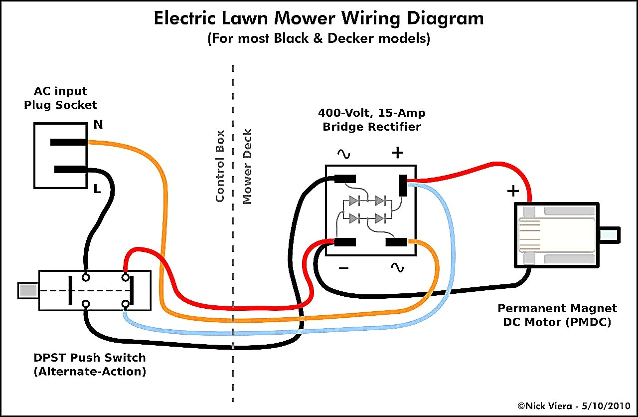
Small Engine Light Wiring Diagram - Complete Wiring Schemas
Photo Credit by: bing.com / wiring diagram motor electric switch electrical century motors light magnetek mower engine lawn drum small mp7 circuit guitar smith way
Dayton 2x440 Drum Switch Wiring Diagram - Wiring Diagram
Photo Credit by: bing.com / drum dayton furnas 2886 r44 unsure terminals couple
Wiring Diagram Taking Into Consideration Electric Motor - Auto Wiring

Photo Credit by: bing.com / reversing leeson diagrams 5hp grizzly justanswer ww2 lift wiringg wagner
Century 1 Hp Motor Wiring Diagram : Century Ac Motor Wiring Diagram / I

Photo Credit by: bing.com / phase lighted rocker ripping kanri u2022 volts wiper fenetre 2020cadillac cleaver schematic capacitor tossing universal volovets tankbig charger
Leeson Motor Wiring Diagram - Free Wiring Diagram

Photo Credit by: bing.com / wiring motor diagram leeson electric hp single emerson motors phase dayton reversible schematic diagrams fan switch drum wagner baldor 230v
G932 Marathon 1hp Electric Wiring Diagram

Photo Credit by: bing.com / wiring diagram electric marathon motor 1hp model hp phase capacitor box clarke run junction always inside use wiringall machine
Leeson Motor Wiring Diagram - Free Wiring Diagram

Photo Credit by: bing.com / wiring motor diagram dayton electric phase drum leeson ac motors century switch hoist capacitor reversing hp single reverse wire forward


