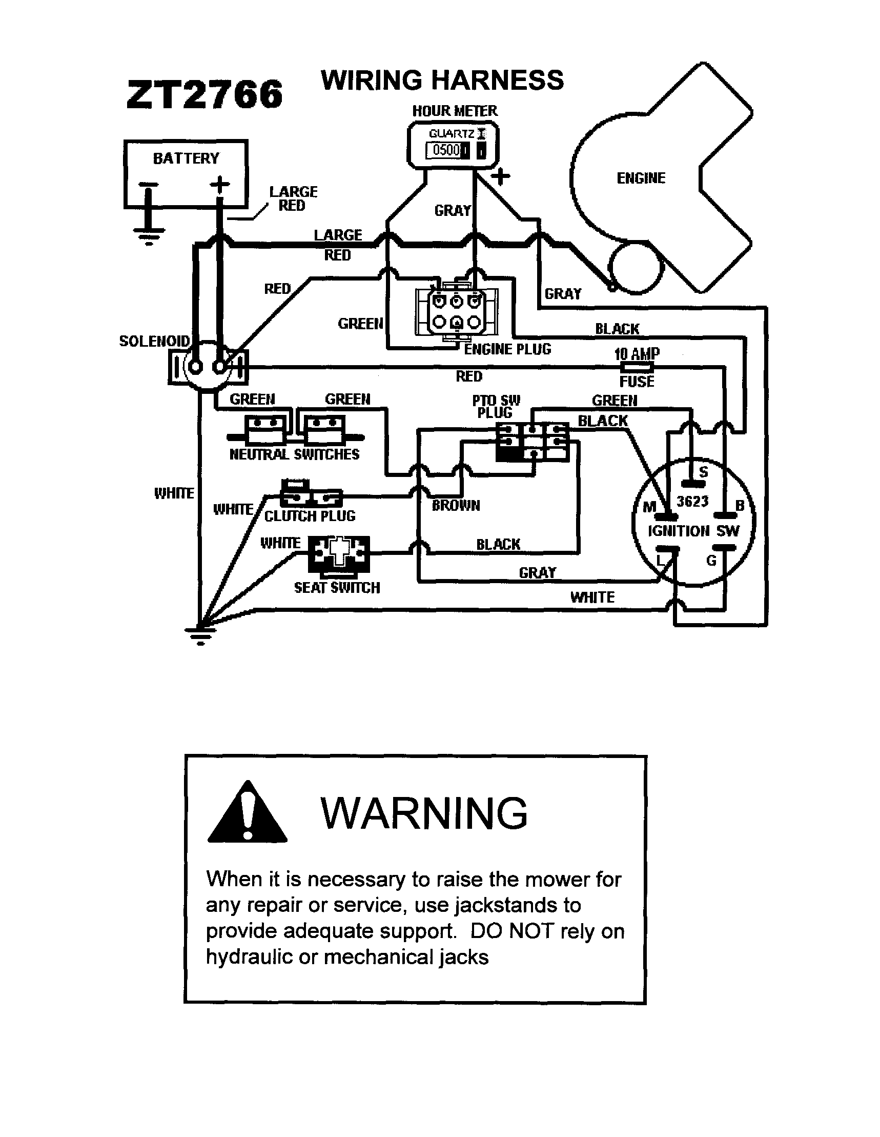
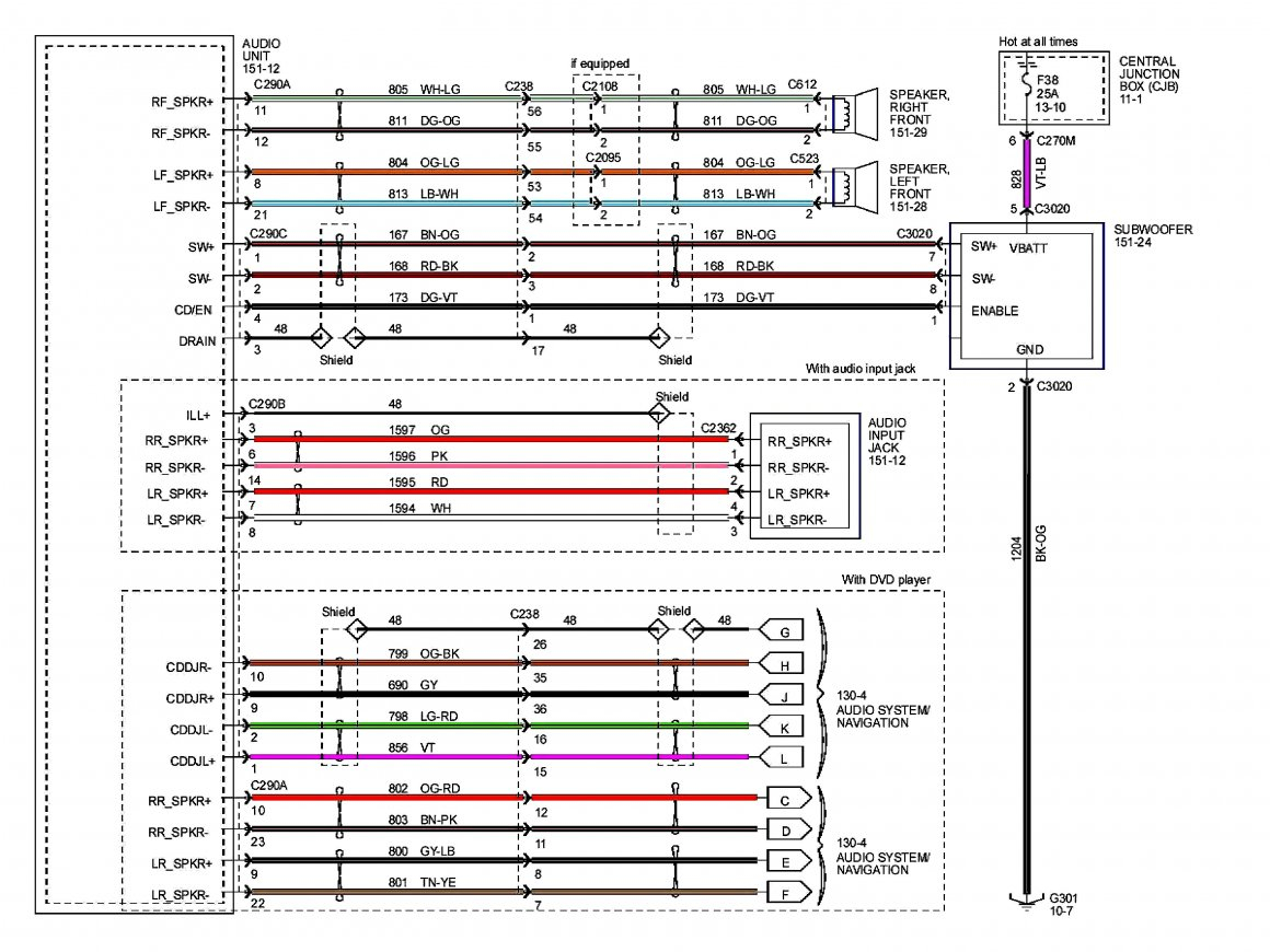
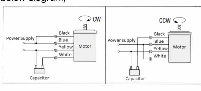
Actuator linear wiring diagram switch rocker 12v choose board wire
Table of Contents
Table of Contents
A linear actuator is a device that is used to create motion in a straight line. A 12V linear actuator is one of the most commonly used actuators, and it is widely used in various applications. When it comes to wiring a 12V linear actuator, it can be a bit challenging, especially for beginners. However, with the right knowledge and guidance, wiring a 12V linear actuator can be a breeze. In this post, we will discuss everything you need to know about 12V linear actuator wiring diagram.
Pain Points
Wiring a 12V linear actuator can be intimidating, especially if you are not familiar with wiring diagrams, circuits, and electrical components. Moreover, if you make any mistake while wiring your linear actuator, it can result in damage to your actuator, controller, or power supply. This can be frustrating and expensive to fix, and can delay your project. Additionally, finding a reliable source for your wiring diagram can be challenging as there are many sources available, and not all of them may be accurate.
The Target of 12V Linear Actuator Wiring Diagram
The target of the 12V linear actuator wiring diagram is to provide a clear and accurate illustration of how to wire your linear actuator. A wiring diagram is a visual representation of the electrical circuit and components. It helps you to understand the connections between the power supply, controller, and actuator. A wiring diagram also helps you to identify any potential errors in your wiring and correct them before they cause damage to your components.
Summary of Main Points
12V linear actuators are widely used in various applications, and wiring them can be challenging for beginners. Pain points include the lack of knowledge about circuits and electrical components, the risk of damaging components, and finding accurate sources for wiring diagrams. The target of the 12V linear actuator wiring diagram is to provide a clear and accurate illustration of how to wire your linear actuator, and help you avoid mistakes.
Explaining 12V Linear Actuator Wiring Diagram
Before wiring your 12V linear actuator, make sure you have the right tools and components, including a power supply, controller, wires, connectors, and of course, your linear actuator. To wire your linear actuator, you need to follow the wiring diagram that matches your controller and actuator. Typically, there are two main types of wiring diagrams for 12V linear actuators: parallel wiring and series wiring.
In parallel wiring, the power source is split, and each component (controller and actuator) receives its own power supply. This is advantageous as it allows you to control each component independently. In series wiring, the controller and actuator are connected in a loop, allowing for better control over the speed and stroke length. However, it requires a larger power supply as both components require the same voltage.
Once you have your wiring diagram, you need to connect your wires and components based on the diagram’s instructions. This can be tricky, especially if you have never wired before. It is essential to follow the diagram carefully and double-check your work before applying power. If everything is wired correctly, your linear actuator should work as expected.
 Common Mistakes to Avoid
When wiring your 12V linear actuator, there are some common mistakes you should avoid. First and foremost, make sure you have the correct wiring diagram for your specific actuator and controller. Secondly, double-check your wiring before applying power. Make sure all connections are secured, and there are no exposed wires. Additionally, make sure your power supply is compatible with your controller and actuator, and that it is providing the correct voltage and amperage. Not following these steps can lead to damage to your components, and ultimately, your project.
 ### How to Troubleshoot Common Issues
If you are experiencing issues with your 12V linear actuator, there are a few things you can check before assuming it is a wiring issue. Firstly, check your power supply and make sure it is supplying the correct voltage and amperage. Consult your actuator and controller datasheets for recommended power supply specifications. Secondly, check your connections and make sure they are secure and not loose. Lastly, make sure your controller is configured correctly and that you are using the correct control signals.
Best Practices for 12V Linear Actuator Wiring Diagram
When wiring your 12V linear actuator, there are a few best practices you should follow. Firstly, always use the correct wiring diagram for your specific controller and actuator. Secondly, double-check your wiring before applying power to avoid damage to your components. Additionally, use the recommended power supply for your components to avoid issues with voltage and amperage. Lastly, always wear proper protective gear when handling electrical components.
Question and Answer
Q: What is the difference between parallel wiring and series wiring for a 12V linear actuator?
A: Parallel wiring splits the power source, allowing each component to receive its own power. Series wiring connects the controller and actuator in a loop, allowing for better control over the speed and stroke length.
Q: Are there any risks involved in wiring a 12V linear actuator?
A: Yes, there are risks involved in wiring a 12V linear actuator. If you make any mistakes while wiring, it can result in damage to your components or even injury to yourself. Always follow proper safety protocols and wear protective gear when handling electrical components.
Q: What are some common mistakes to avoid when wiring a 12V linear actuator?
A: Some common mistakes to avoid when wiring a 12V linear actuator include using the wrong wiring diagram, not double-checking your work, not securing your connections, and not using the correct power supply.
Q: How do I troubleshoot issues with my 12V linear actuator?
A: If you are experiencing issues with your 12V linear actuator, there are a few things you can check. Firstly, check your power supply and make sure it is supplying the correct voltage and amperage. Secondly, check your connections and make sure they are secure and not loose. Lastly, make sure your controller is configured correctly and that you are using the correct control signals.
Conclusion of 12V Linear Actuator Wiring Diagram
Wiring a 12V linear actuator can be a challenging task, especially for beginners. However, by following the correct wiring diagram, using the right tools and components, and double-checking your work, you can wire your linear actuator safely and accurately. It is essential to follow proper safety protocols when handling electrical components, and to troubleshoot any issues before assuming it is a wiring problem.
Gallery
12v Linear Actuator Wiring Diagram - Wiring Diagram Schemas
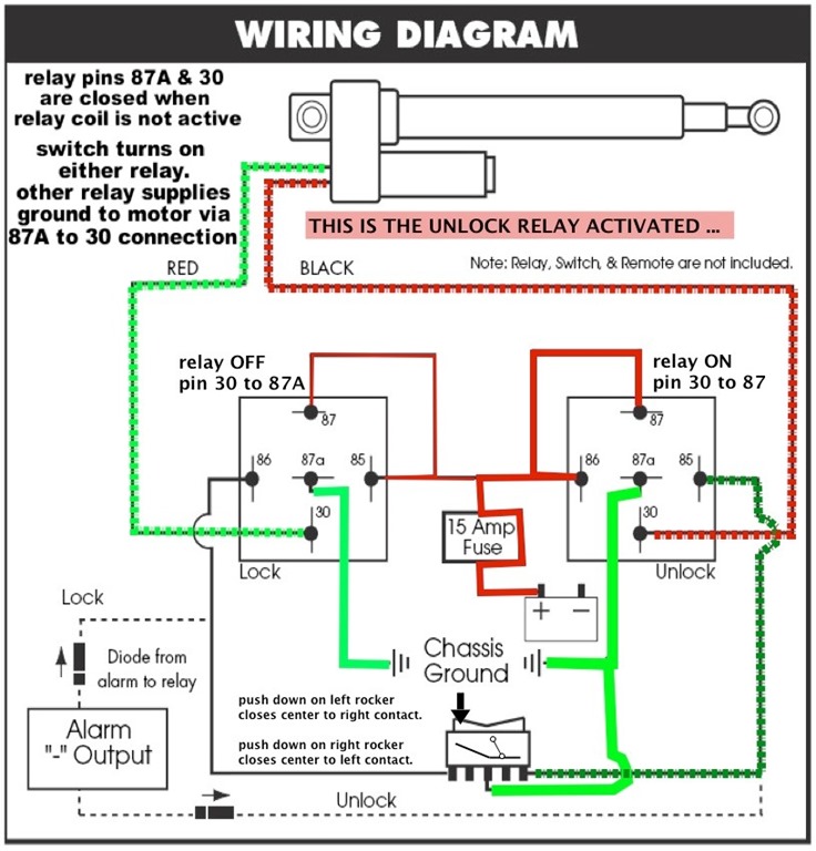
Photo Credit by: bing.com / actuator linear wiring diagram 12v connect arduino
12v Linear Actuator Wiring Diagram - Wiring Diagram Schemas

Photo Credit by: bing.com / actuator linear wiring diagram actuators feedback 12v wire rod linak schematic relay arduino diagrams dc gate related items fa
Linear Actuator Wiring

Photo Credit by: bing.com / polarity circuit actuator limit diagram relay linear reverse switches wiring switch motor switching using electrical relays 12v two channel arduino
12v Linear Actuator Wiring Diagram - Wiring Diagram Schemas

Photo Credit by: bing.com / actuator linear wiring diagram switch rocker 12v choose board wire
12v Linear Actuator Wiring Diagram - Wiring Diagram Schemas

Photo Credit by: bing.com / actuator linear wiring 12v diagram
Warner Linear Actuator Wiring Diagram Gallery - Wiring Diagram Sample
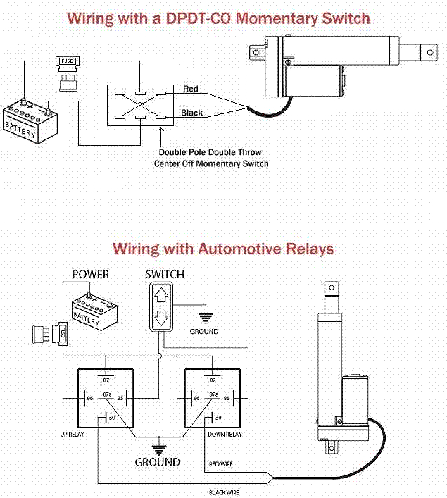
Photo Credit by: bing.com / wiring diagram actuator linear warner switch volt electric motor controller gif schematic speedwaymotors charts static tilt 3v output camber moving
How To Wire Up A Linear Actuator

Photo Credit by: bing.com / actuator rocker neumax instruction terminals
12v Linear Actuator Wiring Diagram - Wiring Diagram Schemas

Photo Credit by: bing.com / actuator linear wiring diagram 12v
12v Linear Actuator Wiring Diagram - Wiring Diagram Schemas

Photo Credit by: bing.com / wiring actuator diagram linear 12v
12 Volt Electric Linear Actuator Wiring Diagrams – Progressive

Photo Credit by: bing.com / actuator rocker 12v electric diagrams
 Common Mistakes to Avoid
