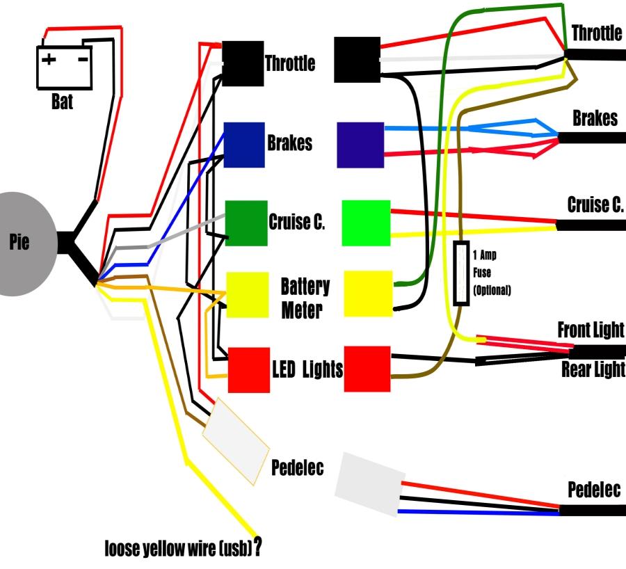
Chanish connecting schematics 12volt prong hotrods
Table of Contents
Table of Contents
If you need to control one or multiple circuits from a single location, a 3 pin toggle switch might be the solution you’re looking for. This type of switch is commonly used in automotive, marine, and industrial applications because of its simplicity and reliability. Whether you’re a DIY enthusiast or a professional electrician, understanding the basics of 3 pin toggle switch wiring diagram can help you avoid common mistakes, save time, and achieve better results.
When dealing with 3 pin toggle switch wiring diagram, one of the main challenges is to identify the correct terminals and connections for your specific application. Depending on the switch type, there might be different ways to wire it, and some of them might lead to unwanted consequences, such as short circuits, blown fuses, or damaged components. Additionally, factors such as the voltage, amperage, and load capacity of the switch and the circuit must be taken into account to ensure safe and reliable operation.
The target of 3 pin toggle switch wiring diagram is to provide a clear and concise overview of the different components, connections, and configurations involved in wiring a 3 pin toggle switch. By following a step-by-step guide and using the right tools and materials, anyone can wire a 3 pin toggle switch safely and efficiently, regardless of their skill level or experience.
In summary, 3 pin toggle switch wiring diagram is an essential topic for anyone who needs to use a toggle switch to control lights, fans, motors, or other devices. By understanding the basics of switch wiring, you can reduce the risk of accidents, increase the performance and durability of your circuits, and improve your overall productivity and satisfaction.
What is 3 Pin Toggle Switch Wiring Diagram and How Does It Work?
When I was working on my car’s lighting system, I realized that I needed a way to turn on and off the headlights, taillights, and fog lights without having to install separate switches for each of them. After some research, I found out that a 3 pin toggle switch would be a perfect fit for my needs. However, I had never worked with toggle switches before, so I was a bit skeptical about my ability to wire them correctly.
After watching some tutorials and reading some articles about 3 pin toggle switch wiring diagram, I felt more confident to give it a try. I learned that a 3 pin toggle switch has three terminals: the common terminal, the normally open terminal, and the normally closed terminal. These terminals are used to make or break the electrical connections between the switch and the circuit. The common terminal is connected to the power source, while the normally open terminal and the normally closed terminal are connected to the load or loads.
Depending on the switch position, the normally open terminal or the normally closed terminal will be connected to the common terminal, allowing or stopping the flow of current through the circuit. This way, you can turn on or off one or multiple devices with a single switch, saving space, time, and money.
How to Wire a 3 Pin Toggle Switch?
To wire a 3 pin toggle switch, you will need some basic tools and materials, such as a wire stripper, a soldering iron, a heat shrink tubing, and some electrical wires. Here are the main steps to follow:
- Disconnect the power source from the circuit where the switch will be installed.
- Install the switch in the desired location, using the appropriate mounting hardware.
- Identify the common, normally open, and normally closed terminals of the switch.
- Determine which terminal is the common (usually the center one) and which one is the normally open or normally closed, depending on your needs.
- Connect the common terminal to the power source of the circuit, using a black or red wire.
- Connect the normally open or normally closed terminal to the load or loads of the circuit, using a blue or white wire.
- Crimp or solder the wire connections, making sure they are tight and secure.
- Cover the wire connections with some heat shrink tubing, to prevent short circuits and moisture. <li.connect and="" back="" circuit="" for="" functionality.="" power="" proper="" source="" switch="" test="" the="" to=""></li.connect>
Some Tips to Keep in Mind
When wiring a 3 pin toggle switch, it’s important to use the right gauge and type of wires for your specific application. If you’re not sure about the wire size and material, you can consult a wiring diagram or a professional electrician. Additionally, you should avoid using flimsy or low-quality switches, as they might fail or break under heavy use or harsh conditions.
Another aspect to consider is the position of the switch in relation to the load or loads. Ideally, the switch should be located as close as possible to the device it controls, to minimize the voltage drop and the interference. If the distance between the switch and the load is too long, you might experience voltage spikes, noise, or performance issues.
Conclusion of 3 Pin Toggle Switch Wiring Diagram
In conclusion, 3 pin toggle switch wiring diagram is an important aspect of electrical systems that require multiple circuits to be controlled from one location. By understanding the basics of switch wiring and following the correct procedures, you can wire a 3 pin toggle switch safely and efficiently, regardless of your level of expertise. Remember to always disconnect the power source before working on electrical circuits, and to use the right tools and materials for your specific application.
Question and Answer
Q: What is the maximum current rating of a 3 pin toggle switch?
A: The maximum current rating of a 3 pin toggle switch depends on the switch type, size, and manufacturer. Some switches can handle up to 30 amps, while others are designed for lower currents. Always check the switch datasheet or consult a professional electrician to determine the appropriate current rating for your specific application.
Q: Can I use a 3 pin toggle switch to control DC circuits?
A: Yes, a 3 pin toggle switch can be used to control DC circuits, as long as the voltage and polarity are within the switch specifications. However, you need to be aware that DC circuits might require additional protection or filtering, depending on their load and environment. Additionally, you should avoid using a switch that is rated only for AC circuits, as it might malfunction or pose a safety hazard.
Q: Can I connect multiple loads to a single 3 pin toggle switch?
A: Yes, you can connect multiple loads to a single 3 pin toggle switch, as long as the total current and voltage of the loads do not exceed the switch specifications. However, you need to be aware that the switch might experience higher wear and tear, and might require additional maintenance or replacement over time. Additionally, you should avoid overloading the circuit, as it might cause safety hazards, such as fires or shocks.
Q: How can I troubleshoot a 3 pin toggle switch that is not working?
A: If your 3 pin toggle switch is not working, you can follow these steps to troubleshoot it:
- Check the wiring connections, making sure they are tight and secure.
- Check the power source and load, making sure they are within the switch specifications.
- Check the switch position, making sure it is not stuck or broken.
- Use a multimeter to test the continuity and resistance of the switch and the circuit.
- Replace the switch if it is detected as faulty, or consult a professional electrician if the issue persists.
Gallery
Three Prong Switch How To Wire It

Photo Credit by: bing.com / switch wiring diagram rocker wire carling off prong toggle three contura carlingswitch terminal explained switches goes comes power into
3 Pin Toggle Switch Wiring Diagram - Collection - Wiring Diagram Sample

Photo Credit by: bing.com / relay
3-Pin SPDT Toggle Switch | MGI SpeedWare

Photo Credit by: bing.com / switch spdt toggle diagram off wiring way 12v metal boat switches car
Switch Basics - Learn.sparkfun - 3 Prong Toggle Switch Wiring Diagram

Photo Credit by: bing.com / prong switches techrush 3pdt control spst sparkfun prewired tonetastic oznium lights
6 Pin Momentary Switch Wiring Diagram - Wiring Diagram Schemas

Photo Credit by: bing.com / switch wiring rocker diagram lighted toggle led volt illuminated 12v prong switches three oznium round wire light red dc diagrams
20 Best How To Wire A 12 Volt 3, Toggle Switch Images - Tone Tastic

Photo Credit by: bing.com / switch wiring toggle diagram wire off volt rocker 12v led lights panel way prong car scion info position switches manual
21 Best 120V Toggle Switch Wiring Diagram

Photo Credit by: bing.com / lighted illuminated carling spst 120v switches prong terminals dpdt vt 10a kcd1 imageservice cloud phl regarding
Toggle Switch Diagram - Wiring Diagram Blog - 3 Prong Toggle Switch

Photo Credit by: bing.com /
Power - Wiring A 3 Position Toggle Switch For Two Devices? - Electrical

Photo Credit by: bing.com / position switch wiring diagram toggle two shawbucker guitar devices power pins electrical pickups stack
3 Pole Toggle Switch Diagram

Photo Credit by: bing.com / chanish connecting schematics 12volt prong hotrods