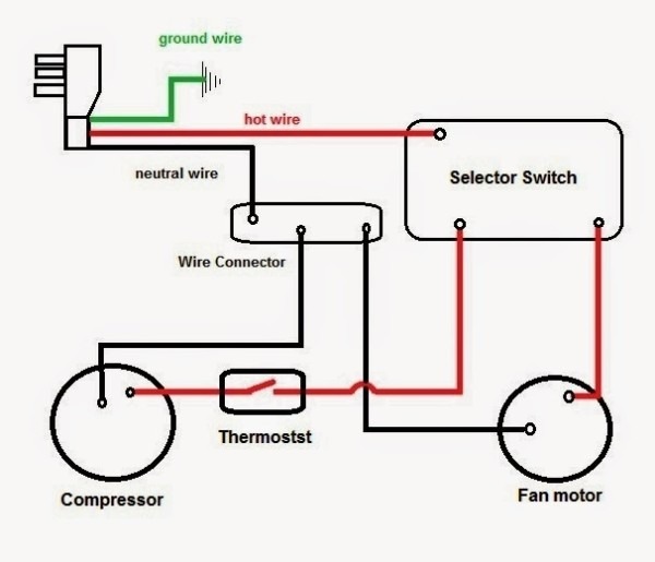
Bosch 5 wire wideband o2 sensor wiring diagram
Table of Contents
Table of Contents
A 4 wire oxygen sensor wiring diagram is essential for anyone who works with cars. The diagram helps them understand how the oxygen sensor works and why it is crucial in a car engine. The schematic diagram shows how the sensor is connected to the car’s computer and how it uses data to regulate the air/fuel mixture in the engine. Without the sensor, the car’s computer would not know how much oxygen is in the exhaust system and could not make necessary adjustments.
The Importance of 4 Wire Oxygen Sensor Wiring Diagram
Working with a car engine can be a difficult task, especially when you don’t know what you’re looking at. However, having a 4 Wire Oxygen Sensor Wiring Diagram can make the process much more straightforward. With the help of the diagram, you can understand how the sensor works and learn how to replace it. The diagram also helps you troubleshoot any problems that might arise with the sensor. The 4 wire oxygen sensor wiring diagram is a fundamental tool that any mechanic should have in their toolbox.
One common problem that people face when dealing with the oxygen sensor is a slow response time. This problem can lead to reduced engine performance, lower fuel efficiency, and increased emissions. The 4 wire oxygen sensor wiring diagram can help you diagnose the problem and provide a solution.
What is the Target of 4 Wire Oxygen Sensor Wiring Diagram?
The target of the 4 Wire Oxygen Sensor Wiring Diagram is anyone who works with car engines, especially mechanics. The diagram can help them understand how the oxygen sensor works and how it is connected to the car’s computer. With this knowledge, they can diagnose problems and provide a solution.
The 4 wire oxygen sensor wiring diagram is also helpful for car enthusiasts who perform their maintenance. They can use the diagram to learn about the sensor and understand how it affects the car’s performance.
Personal Experience with 4 Wire Oxygen Sensor Wiring Diagram
As a mechanic, I’ve come across many issues related to the oxygen sensor. However, having a 4 wire oxygen sensor wiring diagram has made my job much more manageable. The diagram has helped me troubleshoot issues quickly and accurately. It has also helped me explain to customers why the sensor is essential and what they can do to keep it working correctly.
One personal experience I had with the oxygen sensor involved a customer who came in with a Check Engine light on. After performing a diagnostic check, I found that the oxygen sensor was the issue. With the help of the 4 wire oxygen sensor wiring diagram, I was able to replace the sensor and get the customer back on the road quickly.
Common Problems that Occur with 4 Wire Oxygen Sensor Wiring Diagram
The most common problems that occur with the 4 wire oxygen sensor wiring diagram are related to connectivity issues. If the sensor is not connected correctly, it can cause a slow response time, reduced engine performance, and increased emissions. The diagram can help you diagnose the issue and get the car back on the road quickly.
How to Troubleshoot 4 Wire Oxygen Sensor Wiring Diagram
The first step in troubleshooting the 4 Wire Oxygen Sensor Wiring Diagram is to check the connections. Make sure the sensor is connected correctly and that there are no broken wires. You can also try cleaning the sensor with a special sensor cleaner. If the issue persists, you may need to replace the sensor entirely. With the help of the diagram, you can easily diagnose problems and provide a solution.
Replacing 4 Wire Oxygen Sensor Wiring Diagram
If you need to replace the 4 wire oxygen sensor, you should refer to the diagram to ensure you connect the new sensor correctly. You should also follow the manufacturer’s recommendations for installation and calibration. It’s crucial to get the installation right to prevent any issues with the engine’s performance, fuel efficiency, or emissions.
Conclusion of 4 Wire Oxygen Sensor Wiring Diagram
In conclusion, the 4 wire oxygen sensor wiring diagram is essential for anyone who works with car engines, especially mechanics. The diagram helps them understand how the oxygen sensor works and how it is connected to the car’s computer. With this knowledge, they can diagnose problems and provide a solution. The diagram is also helpful for car enthusiasts who want to learn more about how the sensor affects the car’s performance. By having this diagram in their toolbox, mechanics and car enthusiasts can work with confidence and keep cars running smoothly.
Question and Answer
What is an oxygen sensor, and why is it necessary?
An oxygen sensor measures the oxygen content in the exhaust gases and sends a signal to the car’s computer. The computer uses this signal to adjust the air/fuel mixture to maintain the optimal fuel efficiency and reduce emissions.
How do I know if my oxygen sensor is faulty?
The most common symptoms of a faulty oxygen sensor are a Check Engine light, reduced engine performance, lower fuel efficiency, and increased emissions. If you notice any of these issues, you should have your car checked by a mechanic.
How often should I replace my oxygen sensor?
Manufacturers generally recommend replacing the oxygen sensor every 60,000 miles. However, you should refer to your car’s owner’s manual for specific recommendations.
Can I replace the oxygen sensor myself?
Yes, you can replace the oxygen sensor yourself, but you should refer to the manufacturer’s recommendations for installation and calibration. It’s crucial to get the installation right to prevent any issues with the engine’s performance, fuel efficiency, or emissions.
Gallery
4 Wire O2 Sensor Wiring Diagram - Wiring Diagram
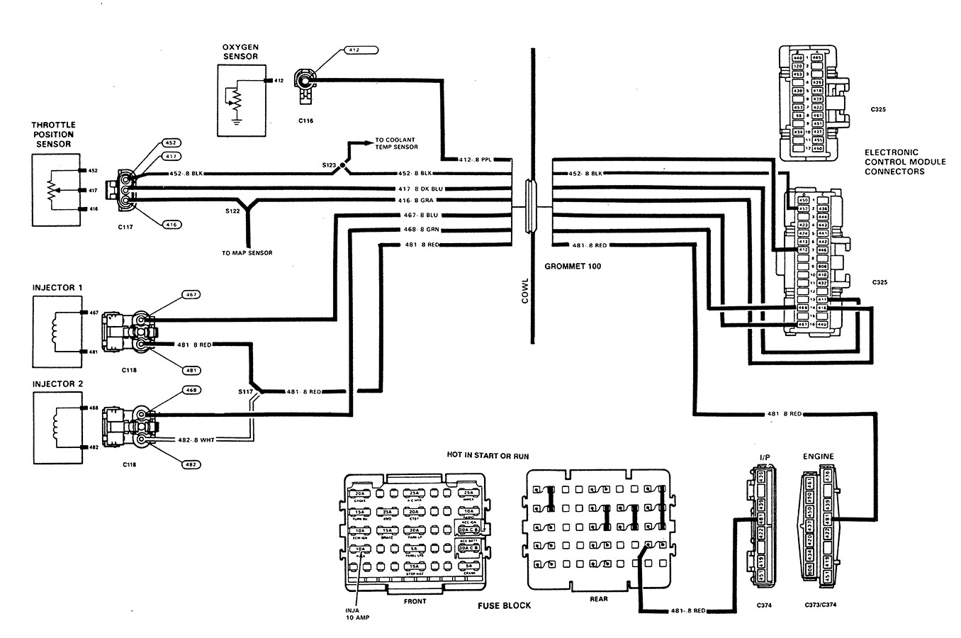
Photo Credit by: bing.com / oxygen
4 Wire Oxygen Sensor Wiring Diagram - Cadician’s Blog
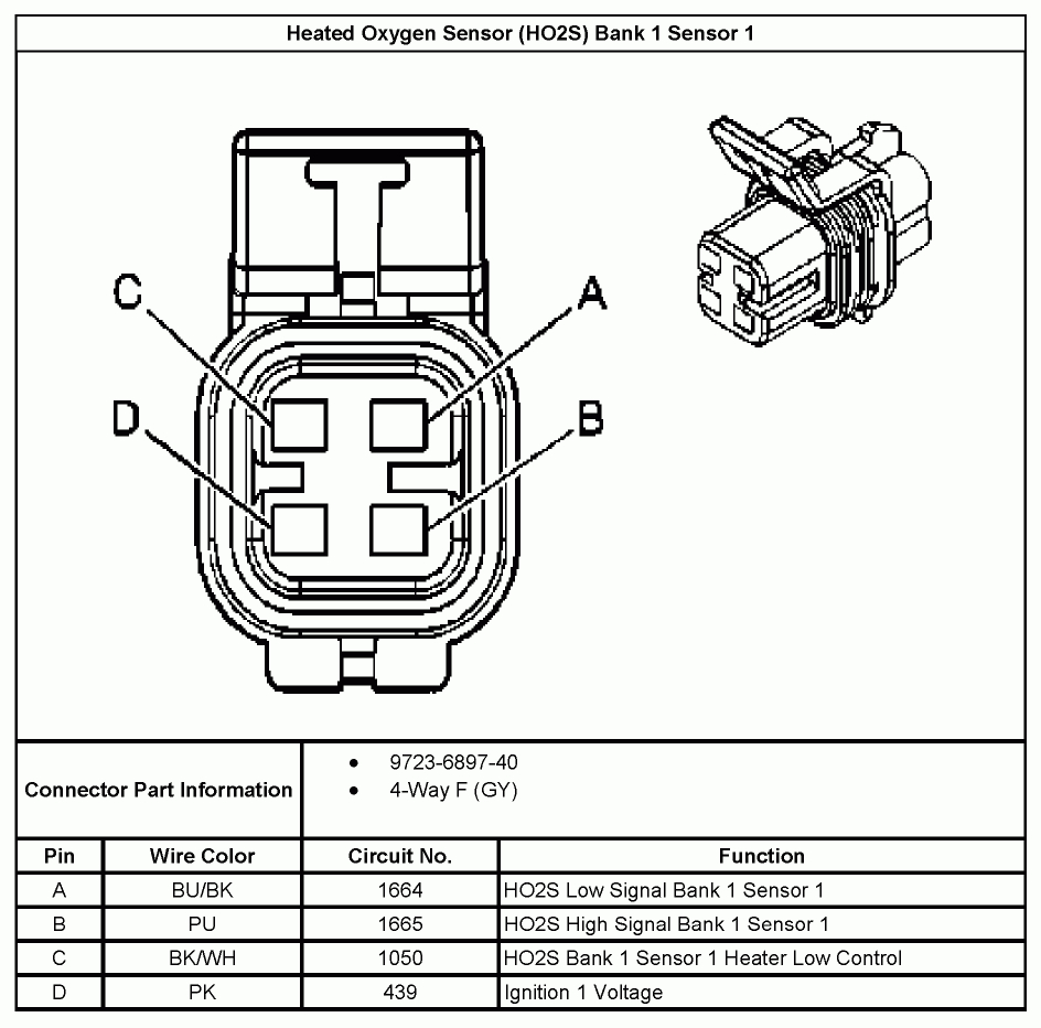
Photo Credit by: bing.com / sensor wiring diagram wire oxygen tahoe ls1 o2 diagrams 2005 engine gm hubs swap lsx plug schematic electrical
4 Wire Oxygen Sensor Wiring Diagram - Cadician’s Blog
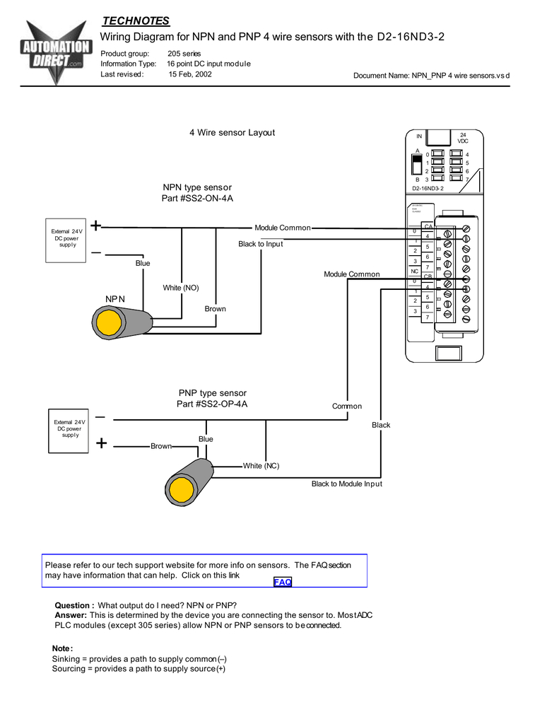
Photo Credit by: bing.com / sensor wiring wire diagram oxygen pnp npn sensors proximity diagrams thumbs d2 transistor automation rockwell catalog type
Bosch 5 Wire Wideband O2 Sensor Wiring Diagram - Wiring Diagram And

Photo Credit by: bing.com / o2 wiring wideband lambda bosch mitsubishi sensors lancerregister reyhan
4 Wire Oxygen Sensor Wiring Diagram - Cadician’s Blog

Photo Credit by: bing.com / sensor wiring diagram wire oxygen o2 library
4 Wire Oxygen Sensor Diagram - Wiring Diagram Name - 4 Wire Oxygen
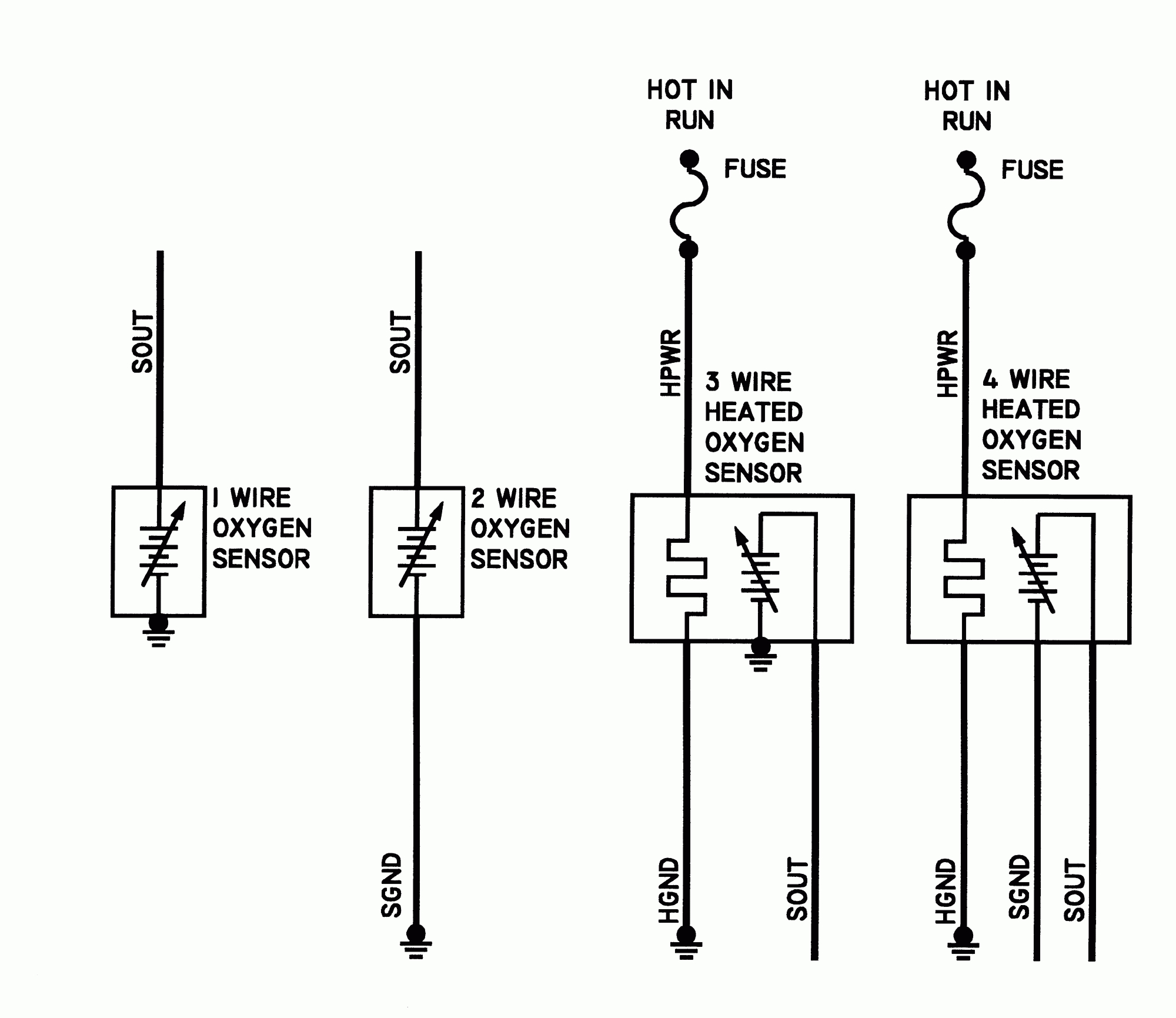
Photo Credit by: bing.com / sensor wiring diagram wire oxygen o2 name repair schematic 2000 sensors universal sedans coupes acura 1994 gm service fig circuits
14 Best Images About O2sensor On Pinterest | Chevy, Colors And Cats

Photo Credit by: bing.com / sensor wire bosch oxygen wiring o2 diagram lambda universal gm quality ebay fake golf motorcycles vw skoda details o2sensor colors
Toyota Rav4 Oxygen Sensor Wiring Diagram - Wiring Diagram
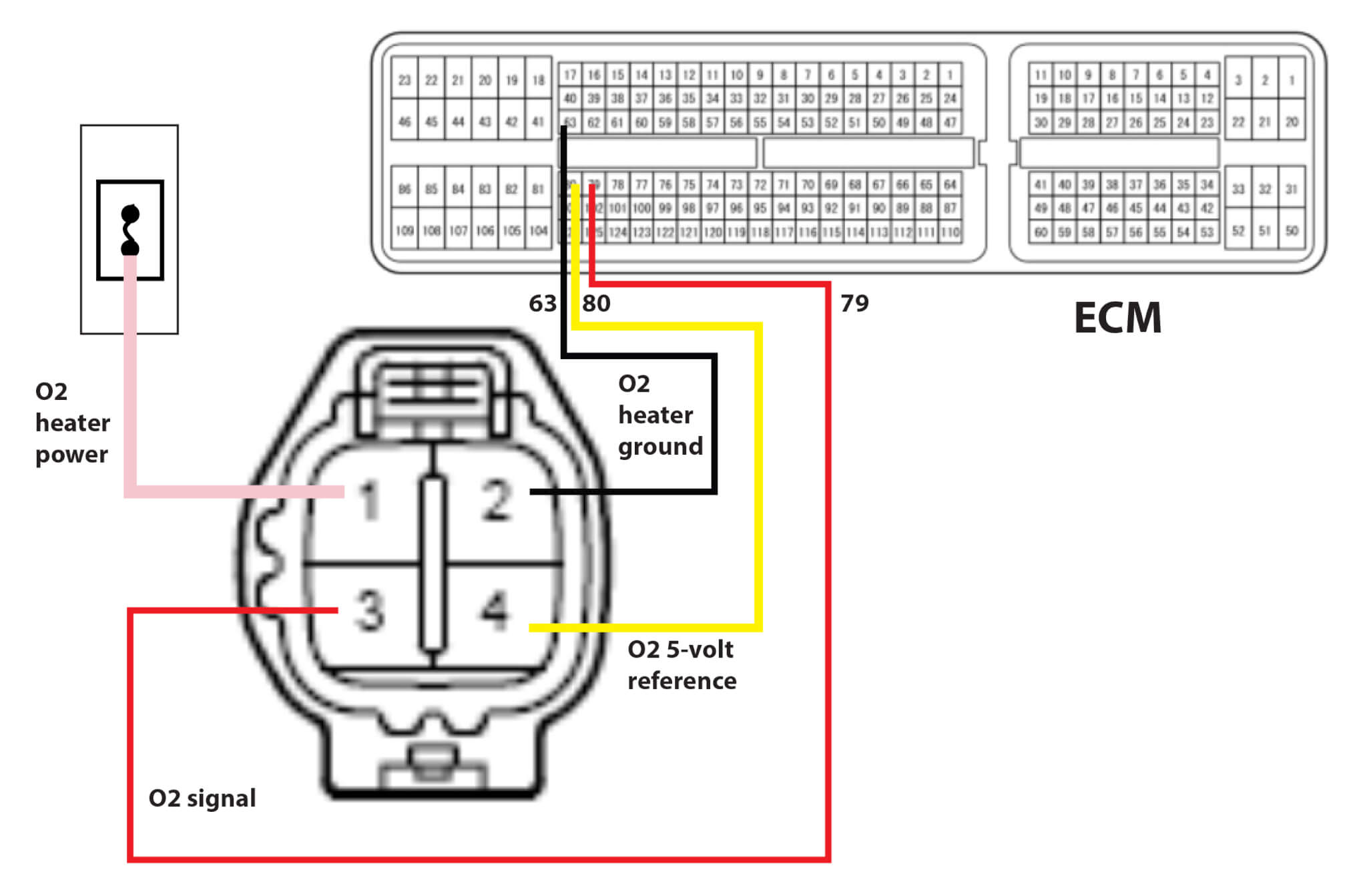
Photo Credit by: bing.com /
4 Wire O2 Sensor Wiring Diagram Downstream Dodge
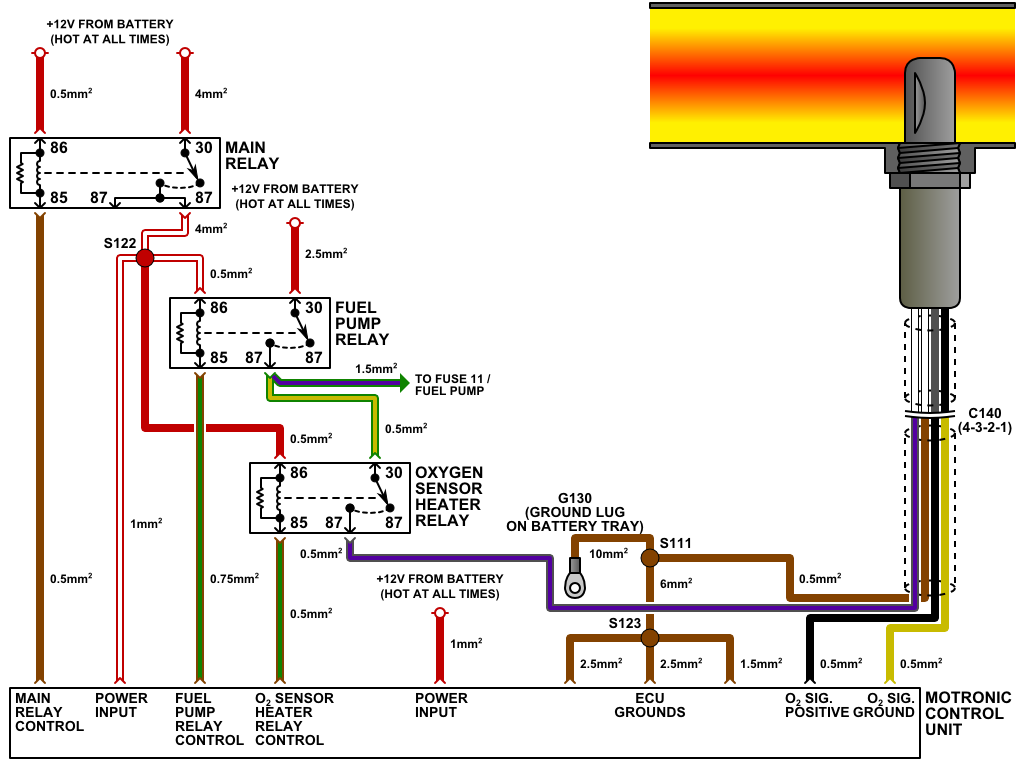
Photo Credit by: bing.com / o2 wideband downstream aem manual stratus oxygen denso rewire trusted heater yotatech civic corolla accord automotorpad
4 Wire Oxygen Sensor Wiring Diagram - Cadician’s Blog
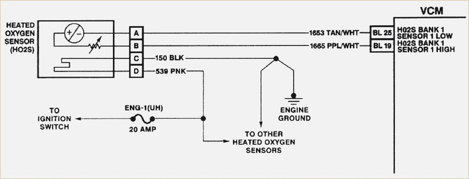
Photo Credit by: bing.com / sensor wiring diagram oxygen wire pinout toyota chevy harness heated nippondenso today repair plug gm fuel map autozone 1994 pickup


