5 way trailer wiring
Table of Contents
Table of Contents
If you’re in the world of electrical wiring, you’ve probably come across 5 pin wiring diagrams. These can be overwhelming and confusing, especially for those who are new to the industry. But fear not, because in this post we will break down everything you need to know about 5 pin wiring diagrams.
Potential Issues with 5 Pin Wiring Diagrams
Often times, those who are not familiar with 5 pin wiring diagrams can feel stressed and overwhelmed when dealing with them. This is because the diagrams can be complex and difficult to understand at first glance. Additionally, if you do not follow the diagram correctly, it can lead to major issues, such as fire hazards or damage to equipment.
What is 5 Pin Wiring Diagram?
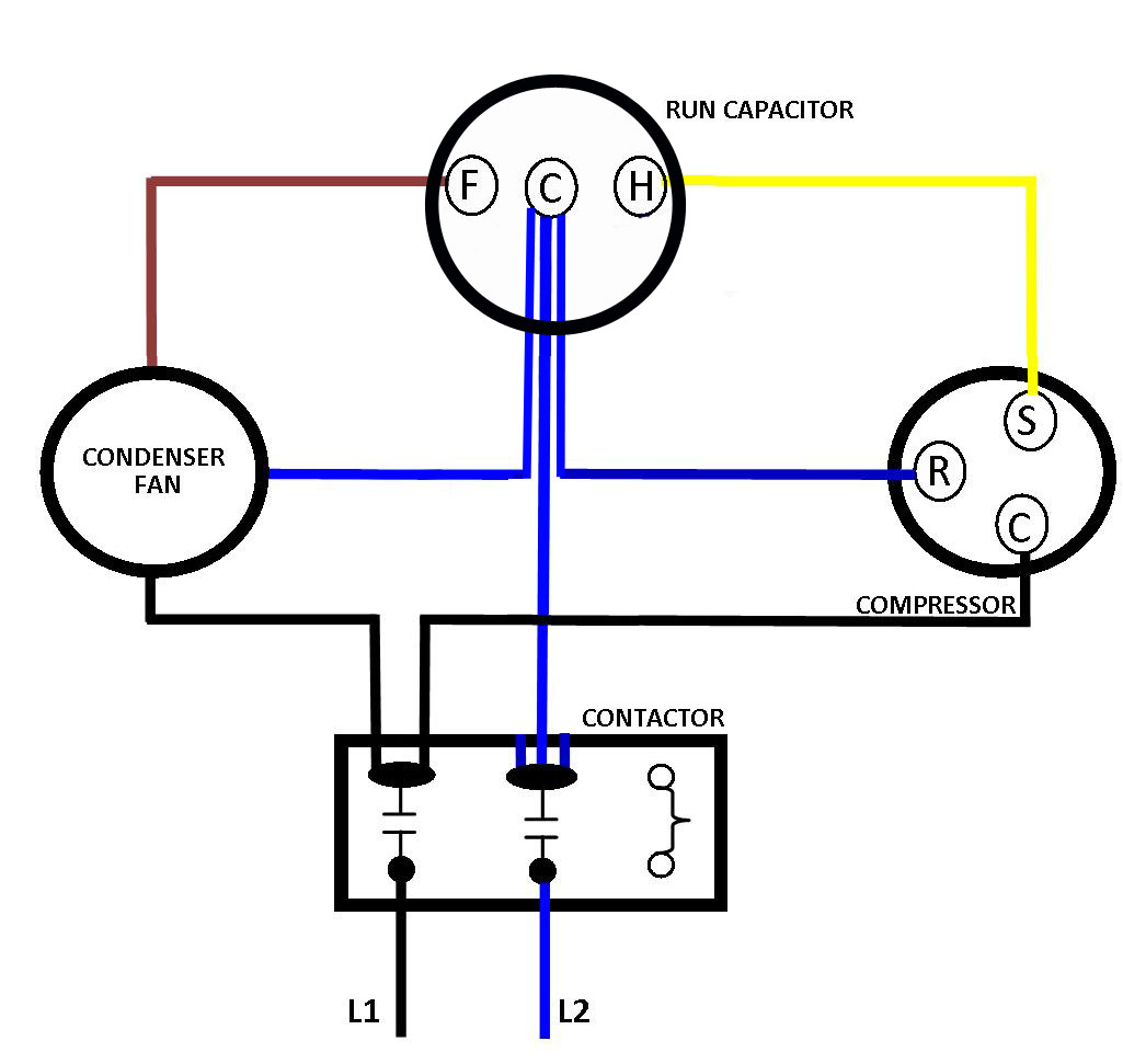
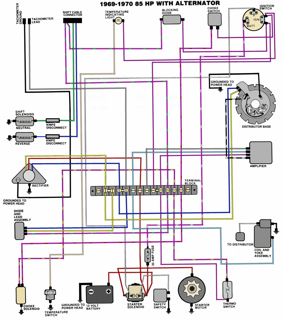
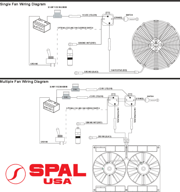
Simply put, a 5 pin wiring diagram is a technical drawing demonstrating how to connect wires in a five-pronged electrical plug or relay. The diagram shows how the wires are connected and where they should go, allowing you to properly install electrical equipment without having any guesswork involved.
Key Insights on 5 Pin Wiring Diagrams
Now that we understand what a 5 pin wiring diagram is, we can dive deeper into the specifics. The diagram typically displays a wiring configuration of specific devices or components, usually in the context of an automobile or trailer. By referring to this diagram, you can quickly troubleshoot and repair any issues within the circuit, saving you time and money in the long run.
Where is 5 Pin Wiring Diagram Used?
One of the most common uses for 5 pin wiring diagrams is in the automotive industry. Cars and trucks have many electrical components that require proper understanding and installation, including light systems, sound systems, and ignition systems, just to name a few. Additionally, 5 pin wiring diagrams are also common in trailer wiring, allowing for safe towing and proper lighting while on the road.
Understanding the 5 Pin Wiring Diagram
The 5 pin wiring diagram itself may seem complicated at first, but when you break it down, it is fairly simple. Each pin represents a specific function and wire within the circuit. These pins are numbered, and in most cases, will be identified with a corresponding color to make things even more straightforward.
Common Components of 5 Pin Wiring Diagrams
There are a lot of components involved in a 5 pin wiring diagram, but some of the most common include relays, power sources, ground sources, and signal wires. Each component plays a necessary role in the circuit, and it is essential that they are all connected properly as to ensure the machinery runs smoothly.
FAQs About 5 Pin Wiring Diagrams
Q: What is the difference between 4 pin and 5 pin wiring diagrams?
A: The main difference between a 4 pin and 5 pin wiring diagram is that the 5 pin diagram includes a fifth wire, which is usually used as a ground source. This allows for safer and more efficient use of electrical equipment.
Q: Can I install electrical equipment without a 5 pin wiring diagram?
A: While it is technically possible to install electrical equipment without a wiring diagram, it is highly recommended that you follow the diagram to ensure proper installation and prevent any potential hazards or complications.
Q: Where can I find a 5 pin wiring diagram?
A: 5 pin wiring diagrams can typically be found in repair manuals or online resources. It is also recommended to consult with an experienced electrician or technician to ensure you are using the correct diagram for your specific needs.
Q: Can I modify a 5 pin wiring diagram to fit my specific needs?
A: While it is technically possible to modify a wiring diagram, it is not recommended. Any modifications to the diagram can lead to unforeseen complications and potential hazards. It is always best to consult with an experienced technician or electrician to ensure proper installation.
Conclusion of 5 Pin Wiring Diagram
Overall, 5 pin wiring diagrams may seem complicated and overwhelming at first, but with proper understanding and implementation, they can be an invaluable tool in the world of electrical wiring. Always consult with an experienced technician or electrician before attempting any installations, and make sure to follow the 5 pin wiring diagram to ensure proper installation and prevent any potential hazards or complications.
Gallery
5 Pin Wire Diagram Pin Rocker Switch Wiring Diagram Image Wiring

Photo Credit by: bing.com / relay wiring diagram amp 30 switch bosch wire fan rocker pertaining 12v relays volt switched january automotive fuse
How A 5 Pin Relay Works - Youtube - Relay Wiring Diagram 5 Pin | Wiring
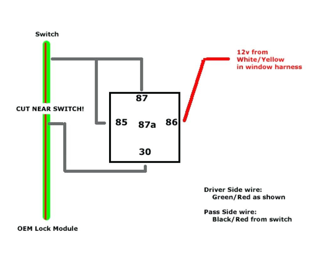
Photo Credit by: bing.com / relay prong denso wire allove popular diagrams
5 Pin Relay Wiring Diagram - Use Of Relay
Photo Credit by: bing.com / relay diagram wiring use wire lights control
3 Phase 5 Pin Plug Wiring Diagram - Wiring Diagram
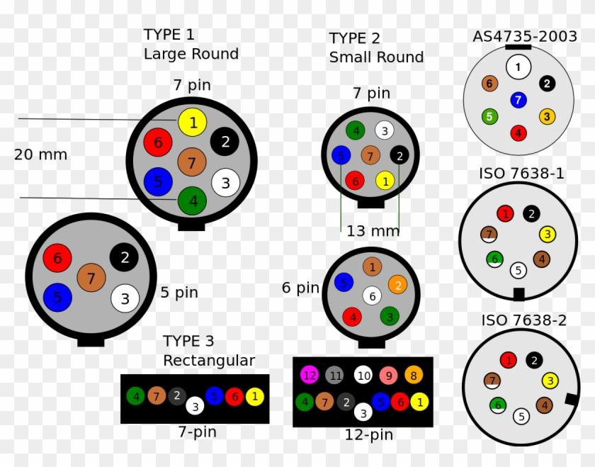
Photo Credit by: bing.com / phase trailer
12V Relay Wiring Diagram 5 Pin - Wiring Diagram
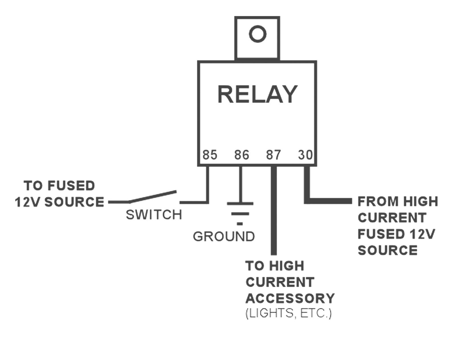
Photo Credit by: bing.com / wiring relay diagram 12v pole solenoid switch prong spotlights rocker volt valid auto amp bosch four dash cam question automotive
Relay Wiring Diagram 5 Pin - Doctor Heck

Photo Credit by: bing.com / push relay isolator 12v diagrams alternator sixmonth annawiringdiagram aftermarket capacitor propane pinout installing
Dorman 5 Pin Relay Wiring Diagram

Photo Credit by: bing.com / wiring dorman
5 Way Trailer Wiring

Photo Credit by: bing.com / wiring trailer diagram wire lights plug round way connector signal africa south schematic right rvupgradestore code brakes vehicle socket turn
Simple 5 Pin Relay Diagram | DSMtuners
Photo Credit by: bing.com / relay diagram wiring simple dsmtuners independence kansas
5 Pin Trailer Plug Wiring Diagram
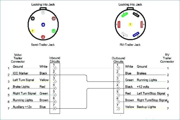
Photo Credit by: bing.com / connector schematic

