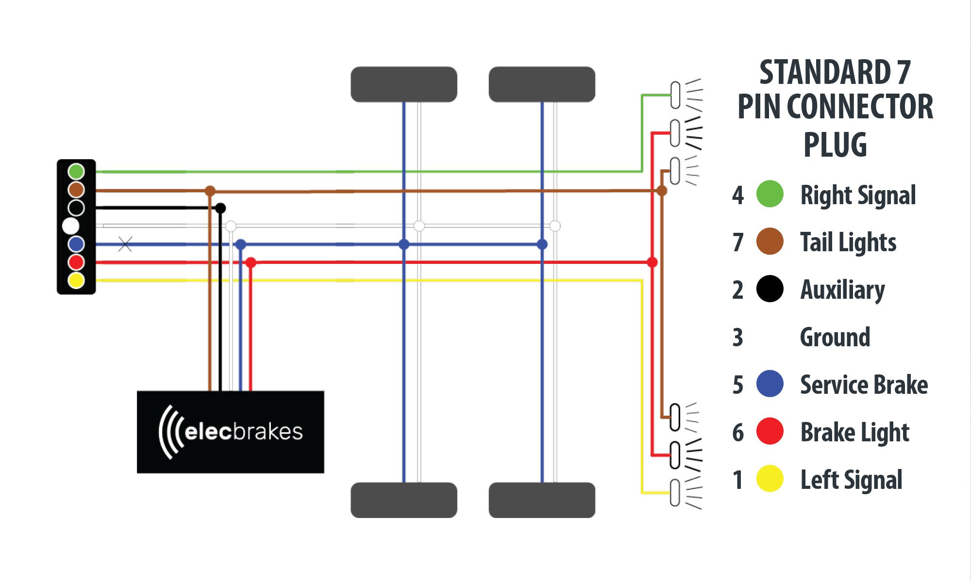
Wiring flasher blinker 1002 softail inserts redesign xs400
Table of Contents
Table of Contents
If you’re a car enthusiast or an auto mechanic, you know that a working turn signal is essential for safe driving. When it comes to vintage cars and trucks with a 6 volt positive ground electrical system, wiring the turn signals can be confusing and frustrating. In this article, we’ll delve into the details of 6 Volt Positive Ground Turn Signal Wiring Diagram and related keywords, so you can understand how to wire your vehicle’s turn signals properly and avoid potential hazards on the road.
The Pain Points of 6 Volt Positive Ground Turn Signal Wiring Diagram
When it comes to wiring turn signals, there are some common pain points that can make the process challenging, especially for those with little experience in automotive electrical systems. One common issue is understanding the difference between positive and negative ground electrical systems and how to properly wire turn signals on a positive ground vehicle. Another challenge is finding the right components that are compatible with a 6 volt electrical system, which can be more difficult to source than parts for a 12 volt system. Additionally, troubleshooting turn signal problems can be time-consuming and frustrating, especially if you’re not familiar with the wiring diagrams and components involved.
The Target of 6 Volt Positive Ground Turn Signal Wiring Diagram
The target of this topic is to provide you with a clear understanding of 6 Volt Positive Ground Turn Signal Wiring Diagram and related keywords, including the difference between positive and negative ground systems, the components involved, and how to properly wire turn signals on a 6 volt positive ground system. We’ll also offer tips and advice for troubleshooting common turn signal issues and finding compatible components for your vintage vehicle.
Summary of Main Points
In summary, 6 Volt Positive Ground Turn Signal Wiring Diagram is a critical component of ensuring safe driving in vintage cars and trucks with a 6 volt positive ground electrical system. Wiring turn signals correctly can be challenging, but understanding the wiring diagrams and the components involved can go a long way in minimizing frustration and avoiding potential hazards on the road. By following the tips and advice provided in this article, you can take the necessary steps to wire your vehicle’s turn signals properly and ensure a smooth driving experience.
Understanding 6 Volt Positive Ground Turn Signal Wiring Diagram
As previously mentioned, one of the main challenges of wiring turn signals on a 6 volt positive ground system is understanding the difference between positive and negative ground electrical systems. In a positive ground system, the positive terminal of the battery is connected to the chassis of the vehicle, while the negative terminal is connected to the electrical components. This is the opposite of a negative ground system, where the negative terminal of the battery is connected to the chassis and the positive terminal is connected to the electrical components.
When it comes to wiring turn signals on a positive ground system, you’ll need to ensure that the wiring and components are designed to work with this type of system. This can include finding turn signal units that are compatible with a 6 volt system, as many modern turn signals are designed for 12 volt systems. You’ll also need to verify that the wiring diagrams you’re using are specific to a positive ground system, as wiring diagrams for negative ground systems won’t be compatible.
One of the most important components of your turn signal system is the flasher unit, which is responsible for flashing the turn signal lights at a consistent rate. When choosing a flasher unit for a 6 volt positive ground system, it’s important to choose one that is designed for this type of system, as using a flasher unit that’s designed for a negative ground system can damage the electrical components of your vehicle.
 Troubleshooting 6 Volt Positive Ground Turn Signal Wiring Diagram
If you’re experiencing problems with your turn signal system, there are a few key areas to check. One common issue is the flasher unit, which can wear out over time and cause the turn signals to malfunction. If the turn signals are flashing erratically or not at all, replacing the flasher unit is a good place to start.
Another common issue is a faulty turn signal switch, which can cause the turn signals to stop working altogether. If you’re unable to get the turn signals to function, checking the turn signal switch and the wiring connections is a good next step.
 ### The Importance of Proper Wiring
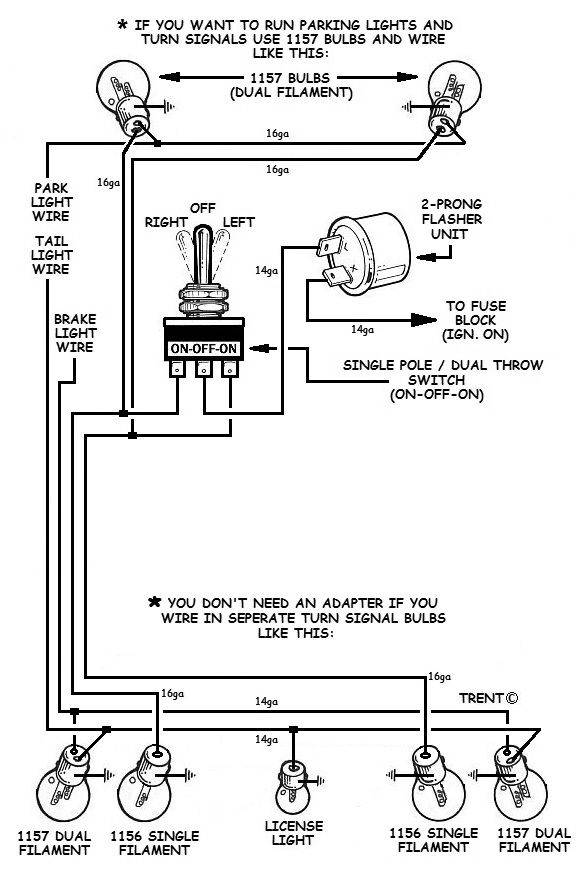
Proper wiring of your vehicle’s turn signals is essential for safe driving and avoiding potential accidents or hazards on the road. By understanding the wiring diagrams and components involved in 6 Volt Positive Ground Turn Signal Wiring Diagram, you can take the necessary steps to ensure that your turn signal system is functioning properly and reliably.
Conclusion of 6 Volt Positive Ground Turn Signal Wiring Diagram
Wiring turn signals on a 6 Volt Positive Ground electrical system can be challenging, but it’s an essential component of ensuring safe driving in vintage cars and trucks. By understanding the difference between positive and negative ground systems, selecting compatible components, and following wiring diagrams specific to a positive ground system, you can wire your turn signals properly and avoid potential hazards on the road. By troubleshooting common turn signal issues and ensuring that your wiring is properly grounded, you can enjoy a smooth and safe driving experience in your vintage vehicle.
Question and Answer
Q: Can I use a turn signal unit designed for a 12 volt system on a 6 volt positive ground system?
A: No, using a turn signal unit designed for a 12 volt system on a 6 volt positive ground system can damage the electrical components of your vehicle. It’s important to use components that are specifically designed for a 6 volt positive ground system.
Q: Why do I need to ground the turn signal components properly?
A: Grounding the turn signal components properly is important for ensuring that the electrical current flows through the circuit correctly. Without proper grounding, the turn signals may not function correctly or could present a hazard on the road.
Q: How do I know if my turn signal switch is faulty?
A: If your turn signals stop working altogether, it could be a sign that the turn signal switch is faulty or that there’s a problem with the wiring connections. Checking the switch and the connections is a good next step in troubleshooting the problem.
Q: Can I use LED turn signal lights on a 6 volt positive ground system?
A: Yes, it’s possible to use LED turn signal lights on a 6 volt positive ground system, but you’ll need to ensure that the wiring and flasher unit are compatible with LEDs. In some cases, you may need to replace the flasher unit with one that’s designed for LED lights.
Gallery
Turn Signal Wiring Diagram | Jrlovvorn | Flickr
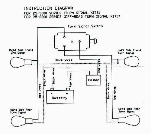
Photo Credit by: bing.com / wiring flasher blinker 1002 softail inserts redesign xs400
Whirlpool Water Heater Wiring Diagram
Photo Credit by: bing.com /
Electrics 65 Split - Trouble With Indicator Wiring! - VW Forum - VZi
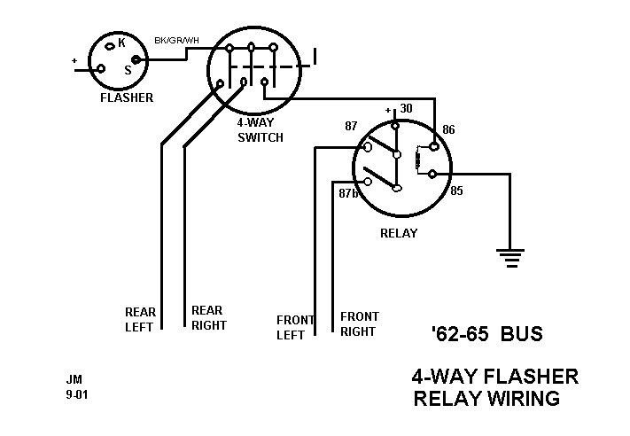
Photo Credit by: bing.com / bus hazard flasher diagram relay switch turn signal way positive volt wiring indicator vw circuit flashers lights terminal ford ground
Wiring Diagram PDF: 1157 Light Bulb Wiring Diagram

Photo Credit by: bing.com /
6 Volt Positive Ground Wiring Diagram | Fuse Box And Wiring Diagram

Photo Credit by: bing.com / wiring diagram solar rv electrical grid trailer positive schematic panel power ground installation travel volt amp system motorhome tie inverter
6 Volt Turn Signal Wiring Diagram - Cogreen

Photo Credit by: bing.com /
Ground Wiring Diagram - Enhandmade
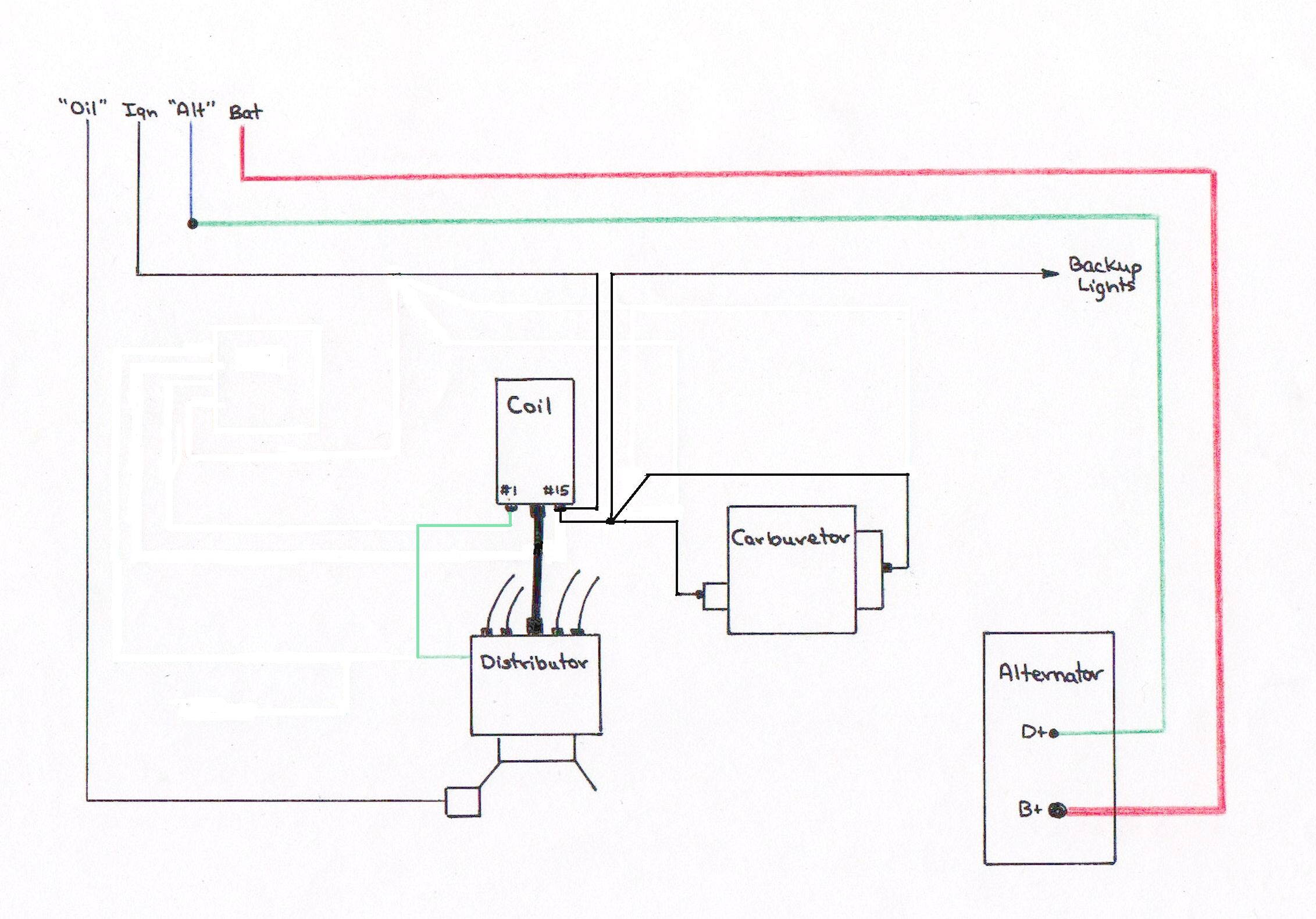
Photo Credit by: bing.com /
️Wiring Diagram 6 Volt Positive Ground Free Download| Gambr.co

Photo Credit by: bing.com /
6 Volt Positive Ground Wiring Diagram - Cadician’s Blog

Photo Credit by: bing.com / ground positive wiring diagram volt battery ford 6v acid lead charger 12v circuit vintage
⭐ 12 Volt Generator Wiring Diagram ⭐ - Misviajes Conlarojita

Photo Credit by: bing.com /


