Brake light turn signal wiring diagram
Table of Contents
Table of Contents
Are you looking to integrate tail lights into your turn signals? Brake Light Turn Signal Wiring Diagram is the solution to all your problems related to wiring turn signals, brake lights, and tail lights. It can be frustrating to figure out the wiring for brake lights and turn signals, but with the right diagram, it can be a breeze.
Pain Points
The wiring of turn signals and brake lights can be a daunting task. With the wires running everywhere and multiple connections to make, it’s not an easy job to connect the brake light and turn signal wires. The biggest challenge is figuring out how to install the turn signal switch, making sure that it operates the turn signals properly and that the brake lights work simultaneously.
Target
Brake Light Turn Signal Wiring Diagram is a comprehensive diagram that illustrates the correct wiring for brake lights and turn signals. The diagram helps to connect all the wires correctly to ensure the proper operation of the turn signals and brake lights. It provides information about the necessary connections, ground wires, and color codes to ensure easy installation.
Main Points
Brake Light Turn Signal Wiring Diagram is essential for easy and accurate wiring of turn signals and brake lights. By following the diagram, it’s easy to connect wires to the brake light switch to ensure the brake lights operate simultaneously with turn signals. Additionally, the diagram provides clear information on the connections between the turn signal switch, tail lights, and brake lights, making it easier to wire the circuits accurately.
Why is Brake Light Turn Signal Wiring Diagram needed?
Brake Light Turn Signal Wiring Diagram is required to provide accurate guidance on the wiring of turn signals and brake lights. The wiring diagram ensures that the wiring and connections required for the proper operation of turn signals and brake lights are correct. With the correct wiring, the turn signals and brake lights operate in sequence and with the correct intensity, providing easy and secure driving for drivers.
Benefits of Brake Light Turn Signal Wiring Diagram
One of the most significant benefits of using Brake Light Turn Signal Wiring Diagram is that it simplifies the wiring and connection process, eliminating guesswork and ensuring that the connections are accurate. This helps to save time and effort during the installation process. Furthermore, it helps to prevent the occurrence of short circuits and electrical fires that can be dangerous while driving.
How does Brake Light Turn Signal Wiring Diagram work?
Brake Light Turn Signal Wiring Diagram is a diagram that provides information on how to connect the wires to the turn signal switch, brake light switch, and tail lights. It details all the connections that need to be made and the wires that need to be connected. The diagram illustrates the connections and provides information on the color codes of the wires that should be connected.
Installation Tips:
The installation process should be done with patience and care. Ensure that all the connections are secure, and there are no loose wires. Take the time to ensure that the connections are correct before connecting the battery. Furthermore, make sure that all the wires are tidy and organized, and the connections are waterproofed to prevent moisture from entering.
Question and Answer
What is Brake Light Turn Signal Wiring Diagram?
Brake Light Turn Signal Wiring Diagram is a diagram that is used to illustrate the wiring and connections that are required for the proper operation of turn signals and brake lights.
Why do I need Brake Light Turn Signal Wiring Diagram?
Brake Light Turn Signal Wiring Diagram is required to provide accurate guidance on the wiring and connections that are necessary for the proper operation of turn signals and brake lights. It ensures that the connections are accurate and eliminates guesswork, simplifying the installation process.
How do I use Brake Light Turn Signal Wiring Diagram?
Brake Light Turn Signal Wiring Diagram provides comprehensive information on the wiring and connections that are necessary for the proper operation of turn signals and brake lights. Follow the diagram carefully to ensure that all the connections and connections are correct.
What can happen if I do not use Brake Light Turn Signal Wiring Diagram?
Without using Brake Light Turn Signal Wiring Diagram, it can be challenging to connect the wires accurately, which can cause the turn signals and brake lights not to operate correctly. Additionally, there can be a short circuit or electrical fires, which can be dangerous while driving.
Conclusion of Brake Light Turn Signal Wiring Diagram
Brake Light Turn Signal Wiring Diagram is a crucial element in the successful installation of turn signals and brake lights. The diagram provides comprehensive information on the necessary connections and wires required for the proper operation of turn signals and brake lights. Ensure that you follow the diagram carefully and take the necessary precautions to prevent electrical risks while connecting the wires.
Gallery
How To Add Turn Signals And Wire Them Up
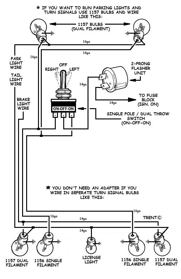
Photo Credit by: bing.com / turn signals wire build
Brake / Running Light / Turn Signal Wiring - Pirate4x4.Com : 4x4 And

Photo Credit by: bing.com / wiring turn brake signal light running lights wire stop 4x4 forum bulb off bdr two
Installing Turn Signals | Electrical Wiring Diagram, Electrical Diagram

Photo Credit by: bing.com / wiring diagram signal turn light brake signals car basic schematic installing motorcycle support electricscooterparts lights trailer cars miller truck trucks
Brake Light Turn Signal Wiring Diagram - Cadician’s Blog
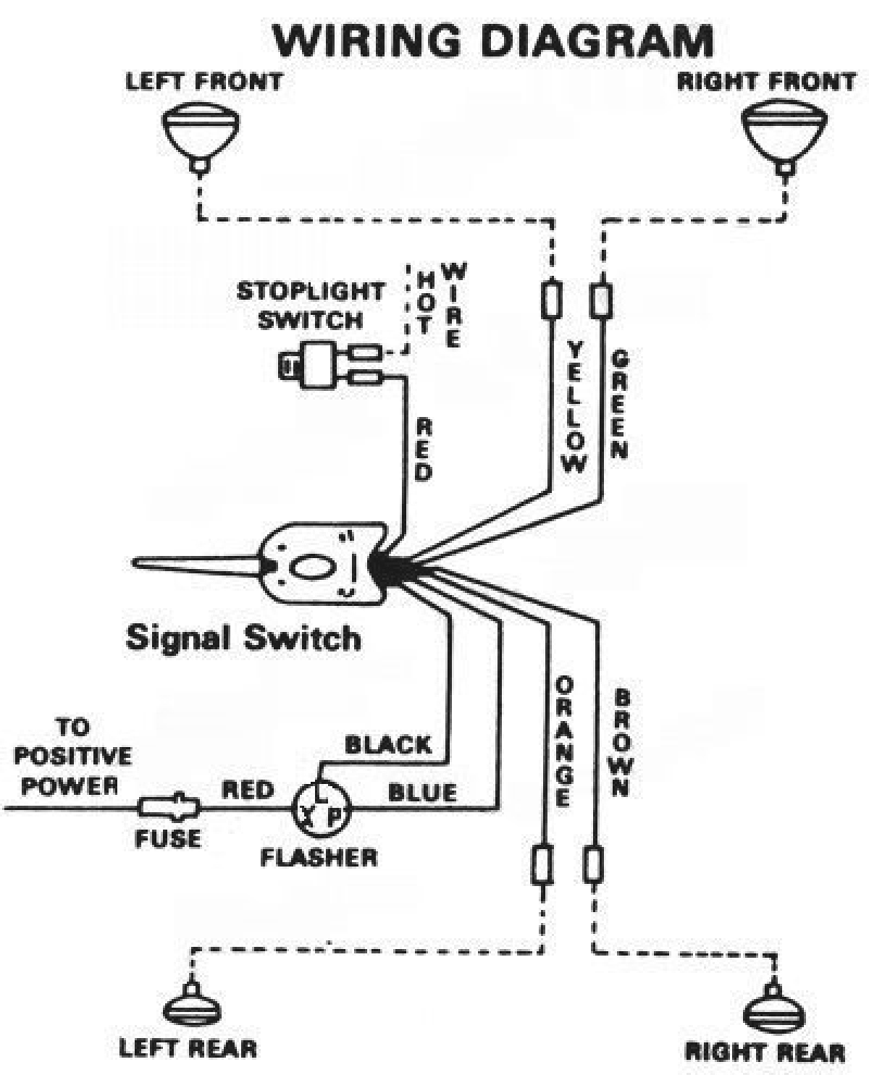
Photo Credit by: bing.com / signal wiring turn diagram switch brake universal light stat lights wire hl cart aftermarket truck golf flasher rod hazard old
Brake Light Turn Signal Wiring Diagram - Database - Wiring Diagram Sample

Photo Credit by: bing.com / wiring signal turn diagram brake light switch lights flasher rod hot volt led prestoimages 12v rat database alone stand kit
Turn Signal Wiring Diagrams / 3 Wire Brake Light Turn Signal Wiring

Photo Credit by: bing.com / stalk ricardolevinsmorales
How Do I Integrate Tail Light Into My Turn Signals? | Yamaha XS650 Forum
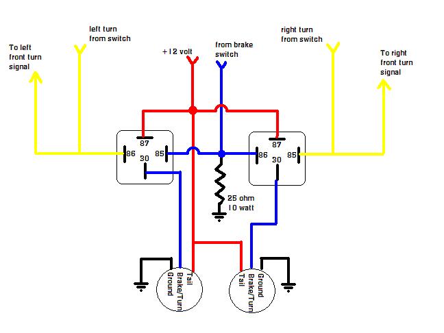
Photo Credit by: bing.com / turn light signals tail relays automotive work led into resistor xs650 two use dual element rear yamaha front need integrate
19 Lovely Wiring Diagram For Trailer Lights And Electric Brakes

Photo Credit by: bing.com / wiring diagram signal turn motorcycle electric brake light electrical bike signals circuit battery blinkers lights wire install hazard schematic support
Brake Light Wiring With 3 Wire Turn Signal Help. | The H.A.M.B.
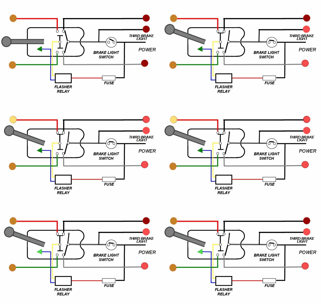
Photo Credit by: bing.com / brake light signal lights wiring wire blinkers turn switch help bulb standalone side diagram relay flasher into 3rd parking per
Brake And Turn Signal Wiring Diagram - Wiring Diagram
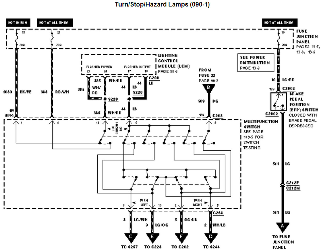
Photo Credit by: bing.com / signals civic 1990 peterbilt diyparty99


