Wiring diagram tach autometer auto meter gauge tachometer
Table of Contents
Table of Contents
If you’re looking for an efficient way to measure a vehicle’s engine speed, you’ve probably come across the Hei Tach Wiring Diagram. A Hei Tachometer is an instrument that measures an engine’s RPM (revolutions per minute) using an electrical signal from the ignition system. This article will discuss the basics of Hei Tach Wiring Diagram and guide you through the process of installing one in your vehicle.
Pain Points
Whether you’re a professional mechanic or a DIY enthusiast, wiring an Hei Tachometer can be a tedious and frustrating task. It’s easy to get lost in a maze of wires and end up with a non-functioning tachometer. The key is to have a clear understanding of the wiring diagram and follow the instructions carefully. Another issue is occasionally not finding accurate information.
Answering the Target
The aim of the Hei Tach Wiring Diagram is to provide a clear and easy-to-follow schematic for connecting the electric components of a Hei Tachometer to the ignition system of a vehicle. The typical Hei Tachometer installation requires five connections: power, ground, TACH terminal, signal input, and dash lighting.
Summary
The Hei Tach Wiring Diagram is a crucial component of successfully installing an Hei Tachometer in a vehicle. It can be a frustrating task, but with careful attention to the wiring diagram’s connections, one can avoid major errors and install a tachometer correctly.
Target of Hei Tach Wiring Diagram
In my personal experience, I’ve found that the wiring diagram is especially important when dealing with older vehicles because the wiring and components can be difficult to access or may not match the installation manual. Installing a Hei Tachometer requires patience, focus, and a clear understanding of the wiring diagram’s connections.
Difficulty in Setting
In my experience, another aspect of Hei Tach Wiring Diagram that can be challenging is getting the tachometer to read the correct engine rpm. This depends on various factors, such as the number of cylinders in the engine and the tachometer’s settings. Once installed correctly, an Hei Tachometer is a reliable tool for monitoring an engine’s RPM.
The Hei Tach Wiring Diagram is an essential tool for anyone planning to install an Hei Tachometer in their vehicle. It provides a clear and easy-to-follow schematic for connecting the electric components of the Hei Tachometer to the ignition system of the vehicle.
Hei Tach Wiring Diagram Components
The Hei Tach Wiring Diagram includes components such as power, ground, TACH terminal, signal input, and dash lighting. An Hei Tachometer is an instrument that measures an engine’s RPM using an electrical signal from the ignition system. You’ll need to connect the signal input wire to the engine’s ignition coil’s negative terminal or the electronic ignition control module’s tachometer output.
Personal Experience with Hei Tach Wiring Diagram
In my experience, it took a while to understand the logic behind the Hei Tach Wiring Diagram. At first, it seemed like a maze of wires and circuits that didn’t make any sense. However, once I got a clear understanding of the connections, it became easier to follow the wiring diagram and complete the installation successfully.
Question and Answer Section
Q. What is the purpose of an Hei Tachometer?
A. The purpose of an Hei Tachometer is to measure an engine’s RPM (revolutions per minute) using an electrical signal from the ignition system.
Q. What are the components of a Hei Tach Wiring Diagram?
A. The components of a Hei Tach Wiring Diagram include power, ground, TACH terminal, signal input, and dash lighting.
Q. What are the common mistakes people make when installing an Hei Tachometer?
A. Common mistakes include incorrect wiring connections, incorrect tachometer settings, and using the wrong signal input wire.
Q. How do I know if my Hei Tachometer is reading the correct RPM?
A. The easiest way to determine this is to use a handheld tachometer and compare it to the readings on the Hei tachometer. Adjust the tachometer settings until it matches the handheld tachometer’s readings.
Conclusion of Hei Tach Wiring Diagram
Wiring an Hei Tachometer can be a challenging task, but with a clear understanding of the wiring diagram’s connections, anyone can successfully install a tachometer. The Hei Tach Wiring Diagram is an essential tool for connecting the electric components of the Hei Tachometer to the ignition system of the vehicle. It’s essential to follow the instructions carefully and understand the tachometer’s settings to get accurate engine rpm readings from the tachometer.
Gallery
Hei Tach Wiring Diagram - Free Wiring Diagram
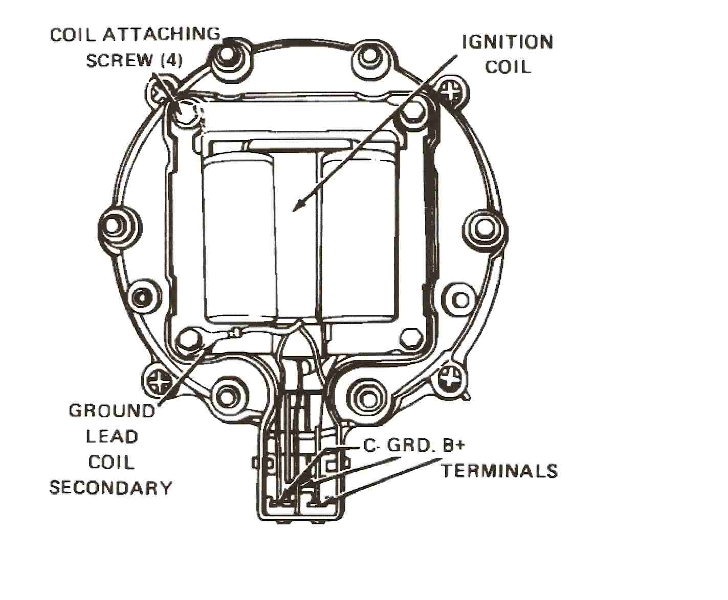
Photo Credit by: bing.com /
Autometer Tach Wiring Diagram - Free Wiring Diagram

Photo Credit by: bing.com / wiring diagram tach autometer auto meter gauge tachometer
Sun Super Tach 2 Wiring Diagram - Cadician’s Blog

Photo Credit by: bing.com / tach sun super wiring diagram hei worksheet comp pro
Vintage Sun Tach Wiring Diagram - Complete Wiring Schemas

Photo Credit by: bing.com / tach autometer tachometer faze tune sunpro manualzz
Chevrolet Hei Distributor Wiring Diagram

Photo Credit by: bing.com / wiring distributor hei diagram chevy 350 gm ignition plug spark schematic cap tach chevrolet starter wire conversion small block diagrams
Tach And HEI Wiring - JeepForum.com

Photo Credit by: bing.com / wiring tach jeepforum
Chevrolet Hei Distributor Wiring Diagram
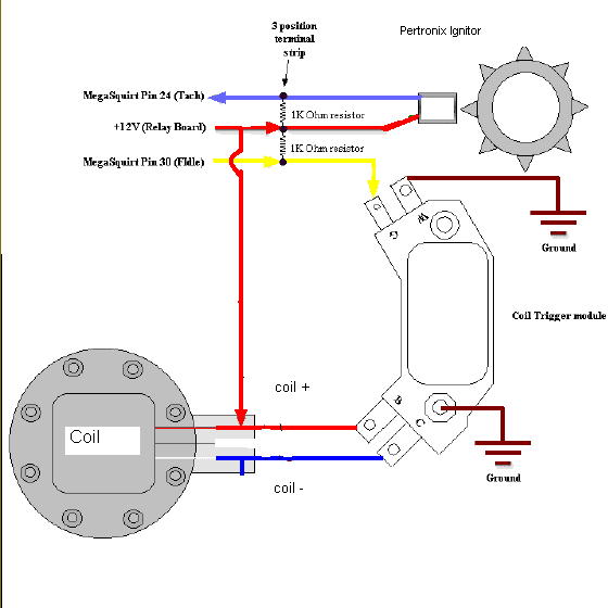
Photo Credit by: bing.com / hei wiring diagram gm distributor coil chevrolet ignition fuel tach schematic injection wire module yahoo search ih affordable articles diy
Ford Hei Distributor Wiring Diagram - Wiring Diagram Schematic

Photo Credit by: bing.com /
Sunpro Tach Wiring Diagram - Wiring Diagram
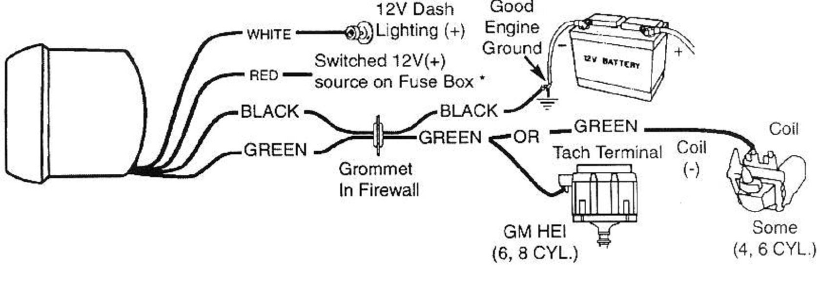
Photo Credit by: bing.com / tach tachometer sunpro autometer vdo autogage schematic
Hei Distributor Tach Wiring Diagram

Photo Credit by: bing.com /

