repair guides
Table of Contents
Table of Contents
If you own a car, chances are you’ve heard of the Idle Air Control Valve Wiring Diagram. This device is integral to the proper functioning of your vehicle, but it can also be a source of frustration for DIY mechanics who aren’t quite sure how to wire it up.
Whether your car is showing symptoms of idle issues or you’re simply trying to take on a new DIY project, understanding the basics of Idle Air Control Valve Wiring Diagram is essential. However, it can be tough to know where to start. In this post, we’ll break down everything you need to know about Idle Air Control Valve Wiring Diagram and how to wire it up properly.
The main target of Idle Air Control Valve Wiring Diagram is to control the amount of air entering your car’s intake system. The valve works to maintain the proper amount of air being fed into your engine while your car is idle, ensuring it doesn’t stall or misfire. If something goes wrong with the wiring of the valve, it can cause a host of issues, from rough idle to stalling and even engine damage.
Now that we’ve covered the basics of Idle Air Control Valve Wiring Diagram, let’s dive deeper into the topic. In this post, we’ll cover everything from how to wire the valve properly to tips for troubleshooting common issues.
Wiring Your Idle Air Control Valve
Wiring up your Idle Air Control Valve can seem daunting at first, but with a little know-how, it’s actually quite straightforward. First, you’ll need to locate the valve itself, which is typically mounted on or near the throttle body. From there, you’ll need to connect the wiring harness to the valve, making sure to follow the proper color-coding.
If you’re still having trouble, there are plenty of resources available online that can guide you through the wiring process step by step. Just remember to take your time and double-check your work to ensure a properly functioning valve.
Troubleshooting Common Issues
Even with proper wiring, your Idle Air Control Valve may still experience issues from time to time. One common problem is a valve that’s stuck open or closed, which can cause issues with idle speed and fuel economy. In this case, you may need to replace the valve itself to fix the issue.
Other common issues include debris buildup in the valve, which can cause it to stick, and wiring issues that can prevent the valve from functioning properly. In these cases, it’s important to carefully inspect the valve and wiring harness to determine the source of the problem.
Understanding Idle Air Control Valve Wiring Diagram
Idle Air Control Valve Wiring Diagram can be a tricky topic to grasp, but with a little practice, you’ll be well on your way to being a DIY auto repair pro. Just remember to take your time, follow the proper color-coding, and troubleshoot any issues as they arise.
Tips for Success with Idle Air Control Valve Wiring Diagram
When it comes to wiring up your Idle Air Control Valve, there are a few key things to keep in mind. First, be sure to use quality wiring components to ensure a reliable connection. Additionally, always double-check your work to avoid loose connections or miswiring. Finally, don’t be afraid to ask for help or consult online resources if you’re feeling unsure.
Question and Answer
Q. How often should I replace my Idle Air Control Valve?
A. While there’s no hard and fast rule, most Idle Air Control Valves last between 50,000 and 80,000 miles. However, if you notice issues with idle speed or poor fuel economy, it may be time to replace the valve.
Q. Can I wire my Idle Air Control Valve without professional help?
A. Absolutely! Wiring up your Idle Air Control Valve is a DIY-friendly task that can be tackled with a little know-how and patience. Just be sure to follow the proper color-coding and take your time.
Q. What tools do I need to wire my Idle Air Control Valve?
A. The exact tools you’ll need will depend on your specific vehicle and wiring setup. However, you’ll likely need a set of wire strippers, crimping pliers, and a multimeter for testing your connections.
Q. How can I tell if my Idle Air Control Valve is faulty?
A. Common symptoms of a faulty Idle Air Control Valve include rough idle, stalling, and poor fuel economy. Additionally, your check engine light may illuminate if there’s an issue with the valve.
Conclusion of Idle Air Control Valve Wiring Diagram
While Idle Air Control Valve Wiring Diagram may seem intimidating at first, with a little practice, anyone can tackle this DIY auto repair project. Whether you’re trying to fix issues with your car’s idle speed or simply looking to expand your DIY know-how, understanding the basics of Idle Air Control Valve Wiring Diagram is essential.
Gallery
| Repair Guides | Electronic Engine Controls | Idle Air Control Valve

Photo Credit by: bing.com / idle control air honda accord prelude valve iac system 1998 engine 1996 2000 repair autozone v6 shown fig car start
Stepper Motor/Idle Air Control Valve MS2 Wiring? - Turbobricks Forums
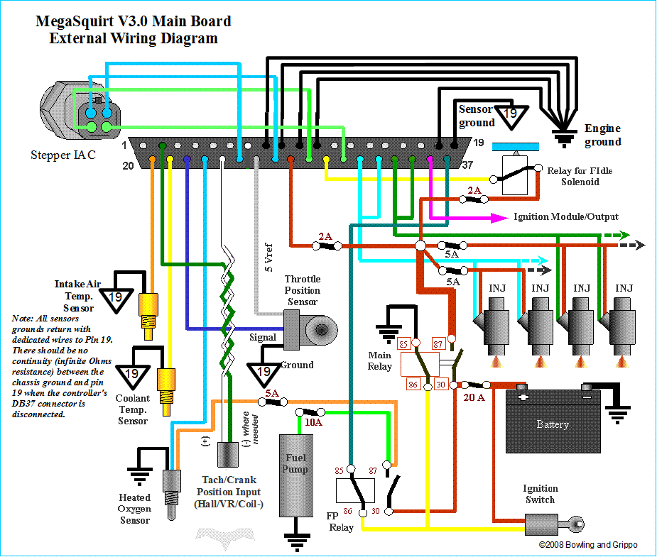
Photo Credit by: bing.com / wiring megasquirt diagram valve ms2 idle control sensor air turbo crank ignition forum wire loom v3 running stepper turbobricks motor
| Repair Guides | Electronic Engine Controls | Idle Air Control (iac

Photo Credit by: bing.com / valve idle control iac air circuit 1996 gm autozone 1l 1994 engine controls corsica testing beretta engines fig 1988 except
Idle Air Control Valve Location Please: Where Is The Idle Air
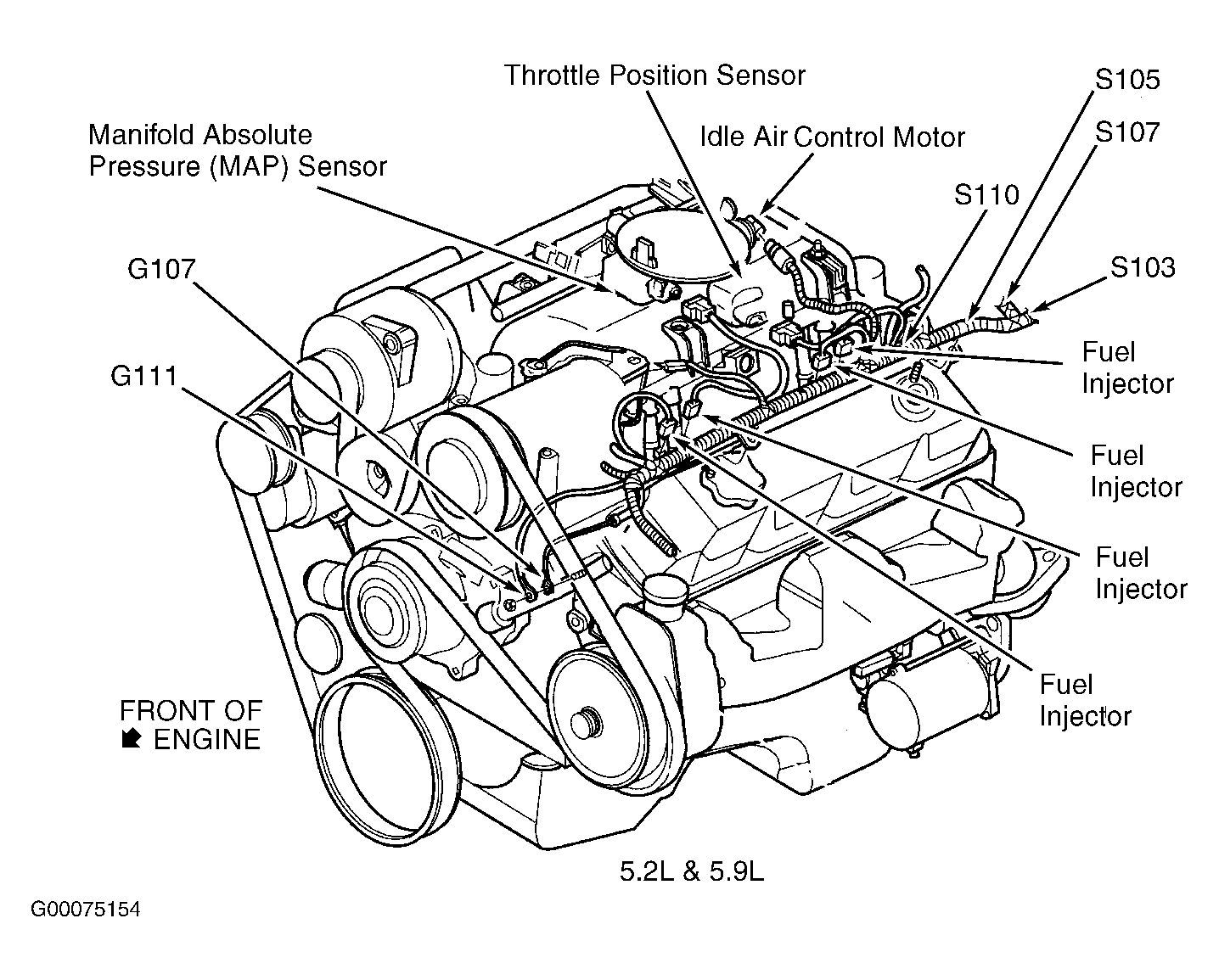
Photo Credit by: bing.com / durango dodge idle air control valve location 1998 dying where please low 2carpros
| Repair Guides | Electronic Engine Controls | Idle Air Control (iac

Photo Credit by: bing.com / iac valve idle control air wiring autozone fig engine 1988 terminal identification vehicles
| Repair Guides | Fuel Injected Electronic Engine Controls | Idle Air

Photo Credit by: bing.com / iac idle valve control air chevy wiring chevrolet 1500 c1500 old engine 1994 tbi autozone testing fig rpm injected fuel
| Repair Guides | Components & Systems | Idle Air Control Valve

Photo Credit by: bing.com / valve wiring control idle air iac autozone mazda harness connections fig
How Does An Idle Air Control Valve Work Ricks Free Auto Repair Advice
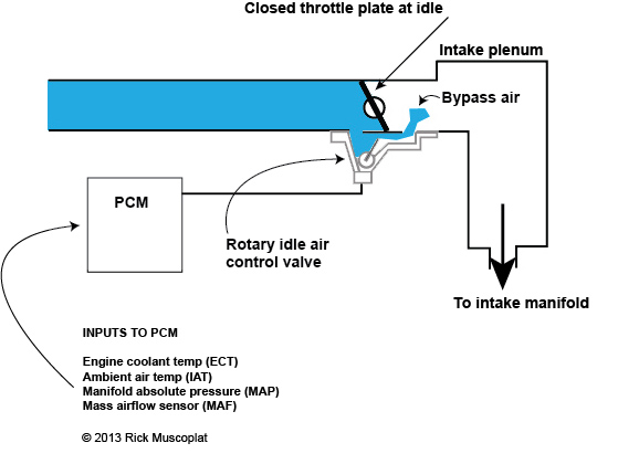
Photo Credit by: bing.com / idle valve air control iac work does rotary wiring gm throttle diagram bypass plate stepper incoming allows stopped around
Wiring And Configuring Outputs On Different Types Of Idle Actuators

Photo Credit by: bing.com / wiring idle air 3pin pwm speed low configuring actuators modular ecus outputs types different using effort configured must which
| Repair Guides | Electronic Engine Controls | Idle Air Control Valve

Photo Credit by: bing.com / air iac wiring valve idle control chevy schematic lumina repair apv 1992 gm tbi engine autozone 1999 fig recently started

