Inverter wiring diagram rv charger power electrical solar transfer switch installing converter camper motorhome caravan generator connect amp board outlet
Table of Contents
Table of Contents
An inverter wiring diagram is an important aspect of any modern office or home that relies on backup power sources. It serves as a guide for proper installation and ensures that both the inverter and UPS system function as intended in the case of a power failure. With the increasing demand for continuous power supply, understanding the wiring diagrams is becoming more vital than ever.
Pain points related to Inverter Wiring Diagram
One of the most significant issues when it comes to wiring an inverter is the complexity that comes with it. Inverter wiring diagrams can be complicated, especially for beginners. Incorrect wiring can lead to numerous problems such as equipment damage, fires, or even injury. In addition, the cost of fixing these mistakes can often be quite high, making it essential to get it right the first time.
The target of Inverter Wiring Diagram
The primary goal of an inverter wiring diagram is to provide a detailed outline of the steps involved in connecting an inverter and UPS system to the home or office’s power supply.
Main points regarding Inverter Wiring Diagram
An inverter wiring diagram is crucial to ensure that the inverter and UPS system function correctly in case of a power outage. Incorrect wiring can cause damage to equipment or even result in injury. The diagram provides a detailed guide on how to connect these systems to the power supply safely. The process can be complicated, but with the right guidance and tools, it can be done efficiently.
Understanding Inverter Wiring Diagram - The Basics
Wiring a home or office inverter system starts by identifying the critical components of an inverter wiring diagram, such as connecting the battery bank, determining the wire sizes and fusing requirements and identifying the proper grounding and protection. Proper grounding is essential in the inverter system, as it protects from short-circuiting and electrical shock. It is also important to take into consideration cable lengths and fuse requirements when designing an inverter system.
Developing an inverter wiring diagram is not always an easy task. My experience in setting up an inverter and UPS system taught me that getting it right the first time requires planning and following the wiring diagram. It is important to note that every inverter wiring diagram should be created to match a specific system’s configuration, ensuring that everything is functional and fully operational.
Enphase Micro Inverter Wiring Diagram
The Enphase Micro Inverter Wiring Diagram is a detailed, comprehensive guide on how to appropriately wire an AC output branch circuit feeder to multiple Micro Inverters. With the ability to connect up to 30 inverters, the guide must follow specific standards for proper functioning.
Installing an Enphase Micro Inverter system necessitates following the correct sequence to ensure the process runs smoothly. To begin, it is necessary to mount the Micro Inverter below the solar panel on the rooftop, followed by routing the branch circuit cables to the junction box, and finally, connecting these cables to the inverter. The Enphase wiring diagram provides a guide to help achieve this sequence successfully.
Understanding Inverter Wiring Diagram - Step-by-Step Guide
The first step involves determining the size of your required inverter and the load it will support carefully. To avoid hazardous electrical fluctuations, ensure to plan accordingly to the most conservative side of the estimated load requirement.
Next, select the suitable battery bank as per the inverter’s requirement, and connect your battery bank via DC fuse or breaker on the array to the positive and negative input connections of the inverter. Ensure that all connections are secured tightly, and cables are correctly trenched to prevent any accidental disconnections.
The Importance of Professional Inverter Wiring
While it may be tempting to do a DIY installation for your home or office inverter system, it is important to understand that it is a significant investment that requires professional installation. Professional installation ensures that the inverter and UPS system are functioning optimally, thus reducing the risk of accidents. An expert installer will also advise you on the type of system that best suits your needs and help you avoid any mistakes that can lead to costly repairs.
Question and Answer
1. What are the risks of incorrect wiring in an inverter system?
Incorrect wiring in an inverter system can lead to equipment damage or harm to people working around the system. It could also result in higher repair costs to fix the mistakes made.
2. How can I ensure that the inverter systems are connected correctly?
The best way to ensure that the inverter systems are properly connected is to use a wiring diagram. If you are unfamiliar with the process, it is best to get the services of a professional to help you with the installation process.
3. Is it necessary to follow wiring diagrams when installing an inverter system?
Yes, it is necessary to follow wiring diagrams when installing an inverter system. Wiring diagrams provide a detailed guide on how to connect the various components safely and effectively.
4. Why is it vital to hire professional installers for my inverter wiring system?
Professional installers have the necessary expertise to install the system safely and effectively. This ensures that it works optimally and reduces the risk of accidents that can result from incorrect wiring or installation.
Conclusion of Inverter Wiring Diagram
With the correct installation of an inverter system, you can effectively power your home or office during power outages. This can only be achieved by following the correct wiring procedures and using reliable wiring diagrams. Remember to always seek the services of a professional installer to ensure optimal performance and safety of the inverter system.
Gallery
House Wiring Diagram For Inverters

Photo Credit by: bing.com / connection inverters kaise hain koppel ud83d
Single Inverter System Wiring
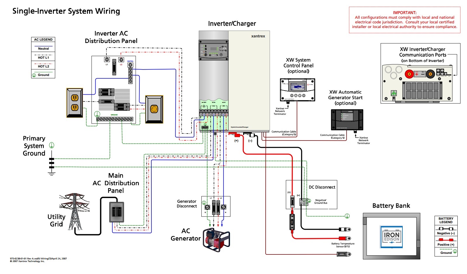
Photo Credit by: bing.com / inverter
Rv Inverter Charger Wiring Diagram - Cadician’s Blog
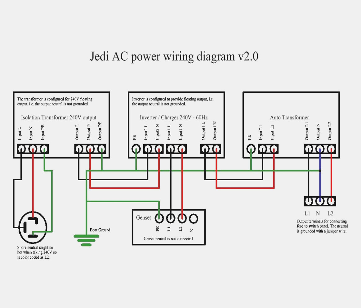
Photo Credit by: bing.com / wiring inverter motorhome xantrex 2020cadillac arrow
Rv Inverter Charger Wiring Diagram - Free Wiring Diagram

Photo Credit by: bing.com / inverter wiring diagram rv charger power electrical solar transfer switch installing converter camper motorhome caravan generator connect amp board outlet
How To Connect UPS & Inverter To Battery And To AC Supply
Photo Credit by: bing.com / inverter diagram connection wiring ups battery connect ac house supply wire mains system batteries current circuit power electrical main installation
Inverter Main Connection | Home Wiring Diagram
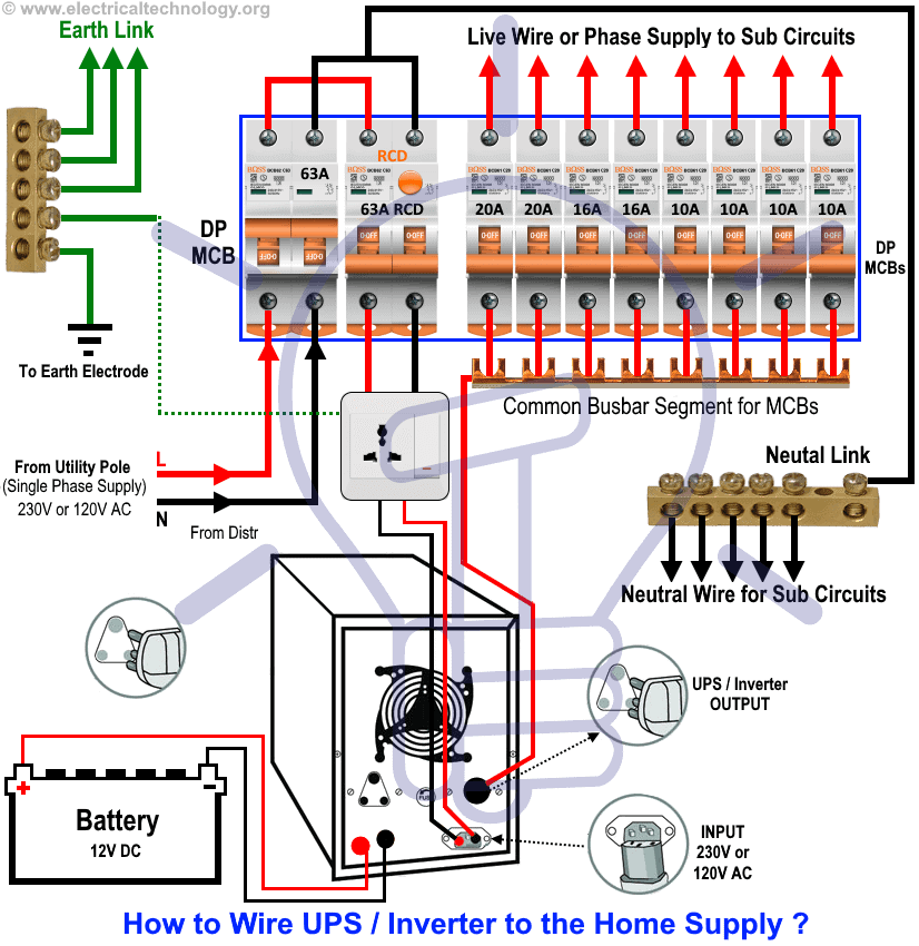
Photo Credit by: bing.com / inverter mains connecting mcb electricaltechnology phase changeover backup input output appliances imageservice relay dari
Understanding Inverter Installations – Project Boat Zen
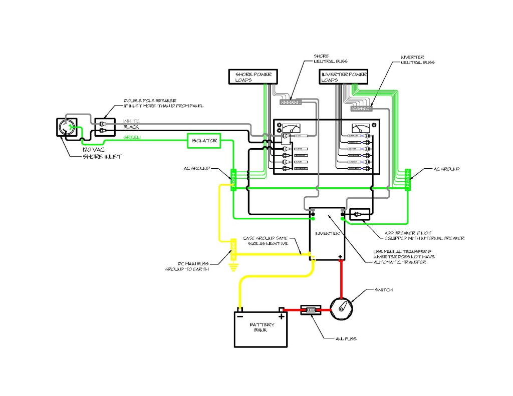
Photo Credit by: bing.com / wiring diagram boat inverter trailer pontoon ground ac ranger schematic harness connection electrical installations power ford fisher great way kicker
UPS & Inverter Wiring Diagram For One Room / Office
Photo Credit by: bing.com / wiring diagram inverter ups switch fronius room shutdown house circuit rapid electrical connection single bypass office wire electricalonline4u board line
Enphase Micro Inverter Wiring Diagram - Free Wiring Diagram

Photo Credit by: bing.com / diagram wiring inverter enphase micro phase single house
Rv Inverter Charger Wiring Diagram - Free Wiring Diagram

Photo Credit by: bing.com / wiring rv diagram battery inverter disconnect switch wire charger amp electrical receptacle rh u2022 typical center fresh exelent circuit most


