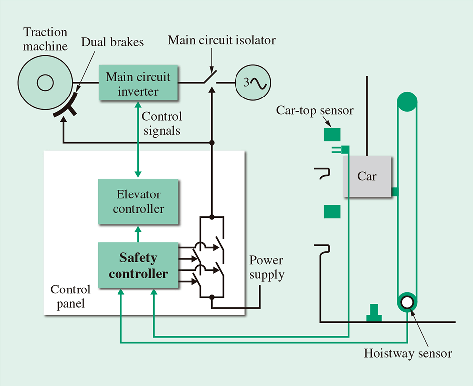
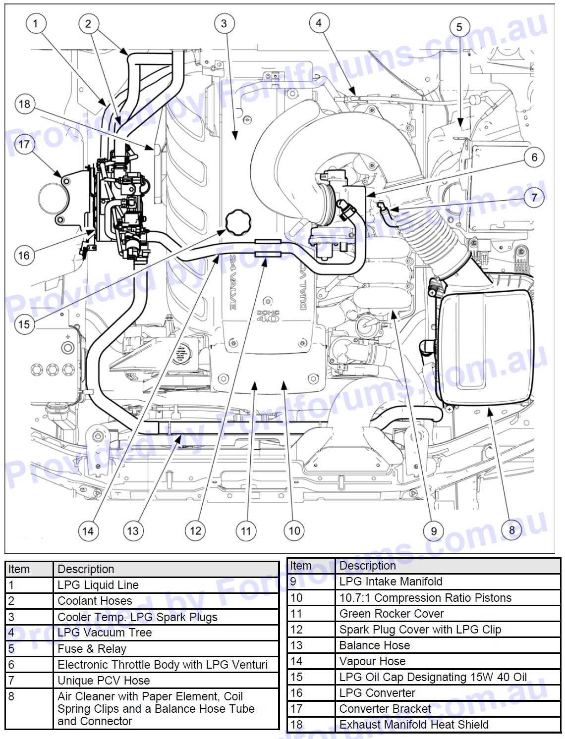
John deere 310g backhoe wiring diagram john deere at326166 wiring
Table of Contents
Table of Contents
Are you working with a John Deere 310 Sg and struggling with the wiring diagrams? Look no further! We have created a comprehensive guide to help you understand the John Deere 310 Sg Wiring Diagram.
The Pain Points of John Deere 310 Sg Wiring Diagrams
Wiring diagrams can be intimidating, especially if you aren’t familiar with the equipment. Understanding the diagrams can be overwhelming and time-consuming. Incorrectly interpreting the diagrams can cause damage to the equipment, which is costly and time-consuming to repair. This is where our guide comes in handy.
The Target of John Deere 310 Sg Wiring Diagram
The ultimate goal of wiring diagrams is to provide a visual representation of the electrical elements of the equipment. Following the wiring diagrams correctly ensures that the electrical systems are in working order and protects against damage to the equipment.
Summary of John Deere 310 Sg Wiring Diagram
In summary, wiring diagrams provide an essential visual tool for understanding the electrical components of your John Deere 310 Sg. Understanding and following the diagrams correctly allows your equipment to function correctly, thereby minimizing the risk of costly repairs.
The Target of John Deere 310 Sg Wiring Diagrams and Related Keywords
When dealing with equipment, understanding the wiring diagrams is vital. Personal experience has shown that trying to diagnose electrical problems without the wiring diagrams can cause more harm than good, which leads to additional repairs and expenses. Not to mention, if the repairs aren’t done correctly, it can lead to safety hazards or downtime in your project. Understanding the wiring diagrams and following them correctly is essential for smooth functioning and the longevity of your John Deere 310 Sg.
Importance of Understanding John Deere 310 Sg Wiring Diagrams
Time and effort spent on following the wiring diagrams correctly will pay dividends in the long run. Ensuring that the electrical components of the equipment are working correctly will minimize the risk of electrical malfunctions and related downtime. Further, an understanding of the wiring diagrams allows you to quickly diagnose problems and reduce the cost of future repairs.
How to Understand John Deere 310 Sg Wiring Diagrams
An easy way to understand the wiring diagrams is to break them down step by step. Start with the larger, more accessible part of the diagram and work your way to the smaller components. It’s essential to pay attention to the symbols and labels used in the diagrams, so you translate them correctly. Utilizing our guide and identifying the wiring diagrams’ symbols and labels can help you become an expert in interpreting them.
Maintenance Tips for John Deere 310 Sg Wiring Diagram
Maintaining the electrical components is essential for the smooth functioning of your equipment. Regular cleaning and checking for wear and tear on wires can save you from future downtime and expensive repairs. Also, ensuring that electrical safety protocols are in place can prevent safety hazards, further diminishing the chance of subsequent downtime and repair costs.
Question and Answer Section of John Deere 310 Sg Wiring Diagram
Question 1: Why are wiring diagrams important?
Answer: Wiring diagrams provide the visual representation of electrical systems, allowing for quick diagnosis and repair. They ensure that the equipment is in working order and adhering to safety protocols.
Question 2: What happens if the wiring diagrams are not followed?
Answer: Failure to follow the wiring diagrams can lead to damage caused by malfunctioning equipment, safety hazards, and downtime.
Question 3: Can a beginner repair the electrical components of the John Deere 310 Sg?
Answer: While beginners can use our guide and interpret the diagrams, it’s best to leave intricate repairs to an experienced technician.
Question 4: How can I ensure that I protect the equipment from voltage surges?
Answer: Installing a voltage regulator can protect electrical equipment from voltage surges.
Conclusion of John Deere 310 Sg Wiring Diagram
Understanding John Deere 310 Sg Wiring Diagrams is essential for the proper functioning of your equipment. Utilize our guide, and you’ll become an expert in interpreting wiring diagrams, leading to a longer lifespan of your equipment, minimizing the risk of expensive repairs and downtime. Never overlook the maintenance of your electrical components and Stick to electrical safety protocols to ensure a safe and efficient working environment.
Gallery
John Deere 310g Backhoe Wiring Diagram - Wiring Diagram Schemas
Photo Credit by: bing.com / backhoe 310d loader 310j steer 310g 310c
John Deere 310G Backhoe Wiring Diagram / JOHN DEERE AT326166 WIRING

Photo Credit by: bing.com / backhoe wiring 310e loader 310g 310sg imageservice eonon 310sj 310c
John Deere 310g Backhoe Wiring Diagram - Wiring Diagram Schemas
Photo Credit by: bing.com / 310g backhoe
John Deere 310G Backhoe Wiring Diagram / JOHN DEERE AT326166 WIRING

Photo Credit by: bing.com / wiring backhoe 310g skid imageservice eonon steer 310sg 310j loader 310sj
John Deere 310G Backhoe Wiring Diagram / JOHN DEERE AT326166 WIRING

Photo Credit by: bing.com / backhoe 310g 310sg patentimages parts 310j 310sj
John Deere 310c Backhoe Wiring Diagram - Wiring Diagram Schemas

Photo Credit by: bing.com / deere backhoe john diagram wiring 310c 310d jd drive light lights
John Deere Service Repair Manuals. Wiring Schematic Diagrams - Free

Photo Credit by: bing.com / bobcat schematic skid steer circuit alternator s250
John Deere 310 G Ecu Wiring Diagram
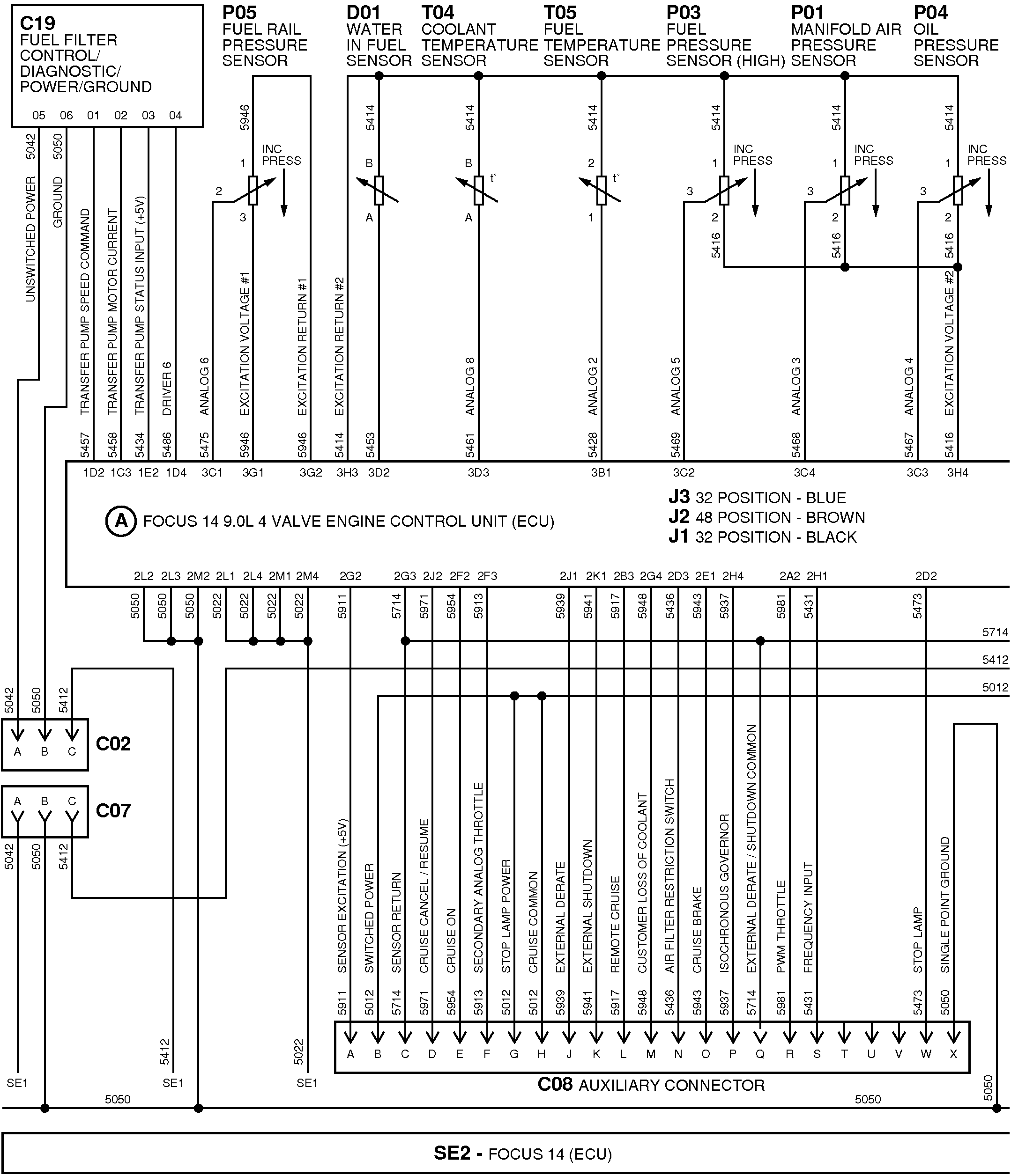
Photo Credit by: bing.com / john deere diagram wiring ecu used
Wiring Harness For Combines
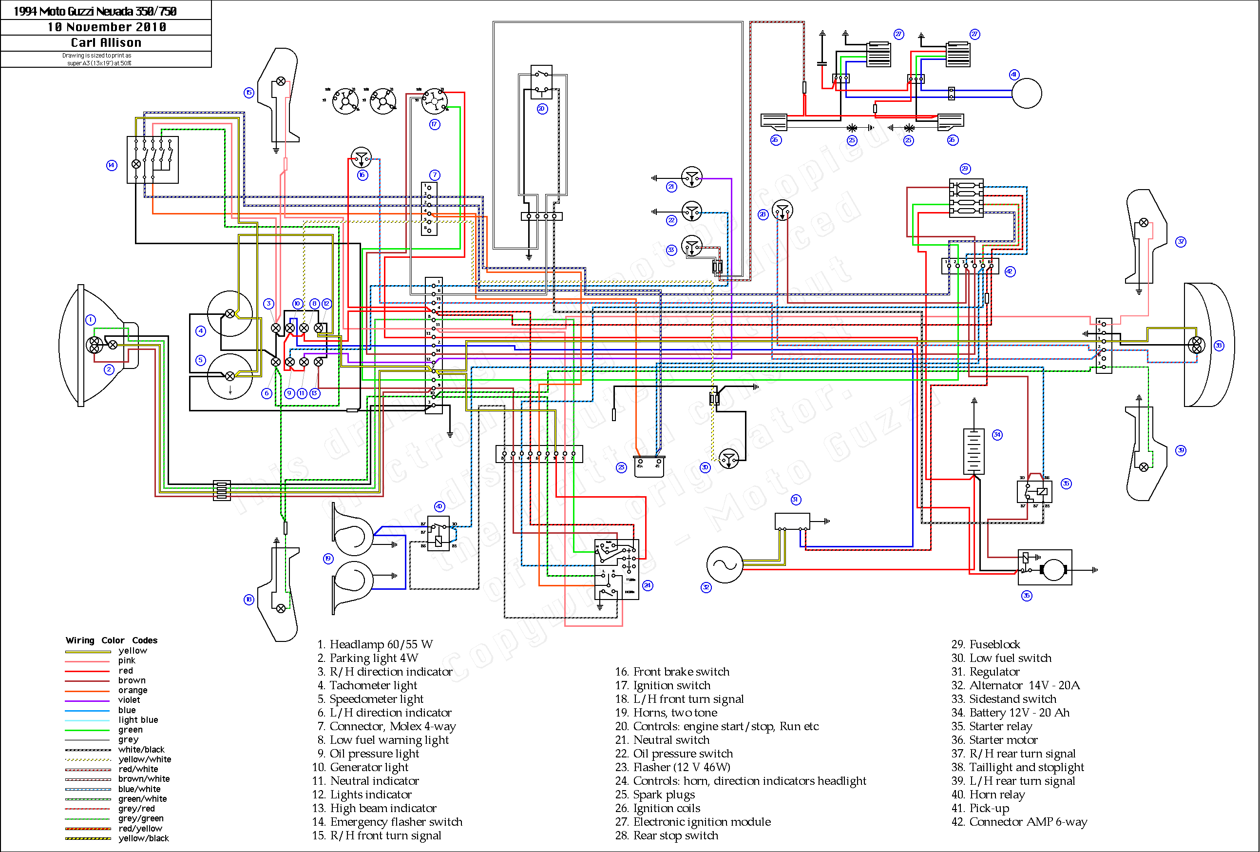
Photo Credit by: bing.com /
John Deere 310 G Ecu Wiring Diagram
Photo Credit by: bing.com / deere john ecu diagram wiring fuses located check line

