Trim mercruiser wiring diagram pump alpha boat cylinders components ii system switch
Table of Contents
Table of Contents
If you own a boat with a Mercruiser engine, you know how vital it is to keep all of its components working correctly. One of the most critical elements of Mercruiser engines is their trim pump, which helps you control your boat’s angle in the water. However, if you are having trouble with the Mercruiser trim pump wiring diagram, you may not be able to get your boat to angle correctly in the water.
The Issues with Mercruiser Trim Pump Wiring Diagram
If you’ve struggled with the Mercruiser trim pump wiring diagram, then you know how frustrating it can be. One of the most common issues with the trim pump is that it can stop functioning correctly, whether it’s not moving at all or moves unevenly. Additionally, the solenoid may also fail, which can cause the trim pump to stop working altogether.
The Target of Mercruiser Trim Pump Wiring Diagram
The primary goal of Mercruiser trim pump wiring diagram is to help you identify the correct connections for the wires of your trim pump. The right connections will help your trim pump work efficiently and prevent any potential issues with the solenoid or other components.
Summary of Key Points on Mercruiser Trim Pump Wiring Diagram
Understanding Mercruiser trim pump wiring diagram is critical to keeping your boat’s trim pump functioning correctly. One of the most common issues with the trim pump is that it can stop working correctly, either not moving at all or moving unevenly, which can be very frustrating for boat owners. By identifying the correct connections in the wiring diagram, you can prevent any potential issues and get the most out of your trim pump.
Explaining the Target - Mercruiser Trim Pump Wiring Diagram
If you’re not familiar with the wiring diagram for your Mercruiser trim pump, it can be a little overwhelming at first. However, the wiring diagram is straightforward once you know how to read it. You’ll typically find the wiring diagram in your engine owner’s manual.
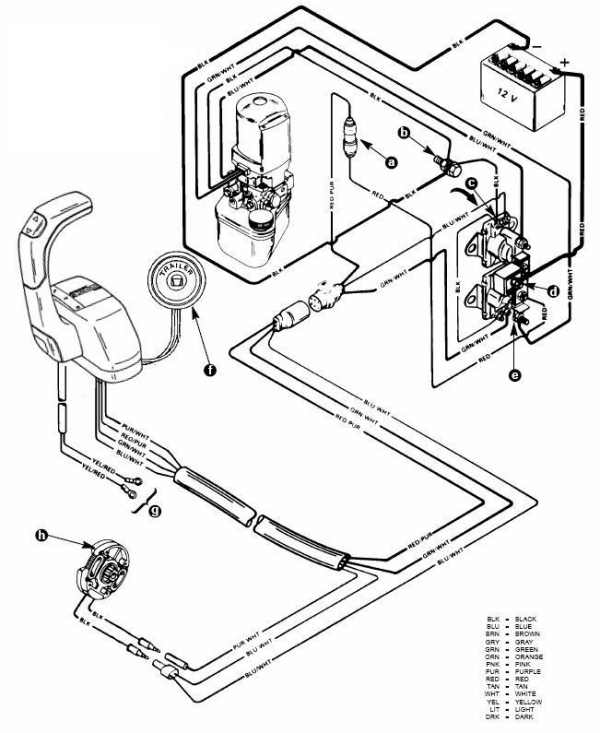
When you first look at the wiring diagram, you’ll see that it is a series of lines and symbols that represent the electrical connections in your trim pump. The lines typically represent wires, and the symbols represent components such as solenoids, switches, and motors. By following the wiring diagram, you can identify each of the components and their connections and ensure that everything is wired correctly.
Mercruiser Trim Pump Wiring Diagram - Common Issues
One of the most common issues with the Mercruiser trim pump wiring diagram is that the electrical connections can become corroded over time. This corrosion can lead to poor electrical connections, which can cause your trim pump to work incorrectly or not at all. To prevent this, it’s essential to keep your electrical components clean and dry at all times. Additionally, it’s important to ensure that all of the connections are tight and secure, which will prevent any potential issues with the solenoid or other components.
Understanding the Components of Mercruiser Trim Pump Wiring Diagram
There are a few key components of the Mercruiser trim pump wiring diagram that you should be familiar with. These include:
- The motor: This is the part of the trim pump that provides the power to lift or lower your boat’s angle.
- The solenoid: This component controls the flow of electricity to the motor and helps move the trim pump up or down.
- The up and down switches: These switches on the control panel allow you to move the trim pump up or down.
Troubleshooting Mercruiser Trim Pump Wiring Diagram Issues
If you’re having difficulty with your trim pump, the first step is to check the electrical connections. Make sure that all of the connections are tight and secure and that there is no corrosion on any of the components. If this doesn’t solve the problem, you may need to replace the solenoid or motor.
Personal Experience with Mercruiser Trim Pump Wiring Diagram
As a boat owner, understanding the Mercruiser trim pump wiring diagram is essential. I’ve had a few instances where my trim pump wasn’t working correctly, and it was frustrating to deal with. By referring to the wiring diagram in my engine owner’s manual, I was able to identify the issue and fix it quickly.
Question and Answer Section on Mercruiser Trim Pump Wiring Diagram
Q: What should I do if my trim pump isn’t moving at all?
A: The first step is to check the electrical connections and make sure that everything is secure and free of corrosion. If this doesn’t work, you may need to replace the solenoid or motor.
Q: Can I replace the solenoid in my Mercruiser trim pump myself?
A: If you have experience with electrical wiring and feel confident in your abilities, you can likely replace the solenoid yourself. However, it’s always best to consult a professional if you’re not sure what you’re doing.
Q: Can the wiring diagram help me identify which component of my trim pump is malfunctioning?
A: Yes, by following the wiring diagram, you can identify each of the components of your trim pump and ensure that they are all working correctly.
Q: How often should I check the electrical connections in my Mercruiser trim pump?
A: It’s a good idea to check the connections periodically, particularly if you notice any issues with the trim pump. Checking the connections once a year is often enough for most boat owners.
Conclusion of Mercruiser Trim Pump Wiring Diagram
Understanding Mercruiser trim pump wiring diagram is critical to keeping your boat’s trim pump functioning correctly. By referring to the wiring diagram in your engine owner’s manual, you can identify any issues with the wiring connections and prevent any potential issues with the solenoid or other components. By taking the time to understand your trim pump’s electrical components, you can get the most out of your boat and enjoy it for years to come.
Gallery
Mercruiser Alpha One Trim Pump Wiring Diagram - Wiring Diagram

Photo Credit by: bing.com / mercruiser quicksilver tilt throttle tankbig outboard solenoid
Mercruiser Alpha One Trim Pump Wiring Diagram - Wiring Diagram
Photo Credit by: bing.com / mercruiser solenoid
Wiring Diagram For 3 Button Single Solenoid Trim Pump For Mercruiser

Photo Credit by: bing.com / mercruiser pump solenoid penta j1171 sae
Mercruiser Tilt Trim Wiring Diagram

Photo Credit by: bing.com /
I Have A Mercruiser Alpha 1 (1996). The “up” Trim Does NOT Activate The

Photo Credit by: bing.com / wiring trim diagram mercruiser mercury motor volt boat wire pump alpha golf cart solenoid ezgo go club engine car ez
Wiring Diagram For 3 Button Single Solenoid Trim Pump For Mercruiser

Photo Credit by: bing.com / mercruiser dumb sender alternator offshoreonly
Mercruiser Oildyne Trim Pump Wiring Diagram

Photo Credit by: bing.com / trim mercruiser wiring diagram pump alpha boat cylinders components ii system switch
The Trim On My Merc Cruiser Wont Go Up Or Down. The Buton Just Goes

Photo Credit by: bing.com / diagram wiring trim mercruiser switch limit engine tilt alpha ray sea down gen sterndrive stingray stern drive boat pump 2007
Wiring Diagram For 3 Button Single Solenoid Trim Pump For Mercruiser

Photo Credit by: bing.com / mercruiser solenoid tilt drives does offshoreonly
Alpha 1 Outdrive Schematic

Photo Credit by: bing.com /


