Mercury 8 pin wiring diagram
Table of Contents
Table of Contents
If you are a fan of boating or have owned a boat, then you probably know how frustrating it can be when your Mercury outboard gauge wiring diagram is not working properly. You may have difficulty getting accurate readings or your gauge may not be working at all, causing you to miss important data about your boat’s performance. In this post, we will explore the topic of Mercury outboard gauge wiring diagrams and provide some helpful tips to get your system up and running smoothly.
Pain Points Related to Mercury Outboard Gauge Wiring Diagram
Owning a boat can be a pleasure, but it comes with its share of headaches. One of the biggest pain points is dealing with issues related to your Mercury outboard gauge wiring diagram. If your system is not working correctly, you may have trouble determining your boat’s speed, fuel level, or engine power, which can be frustrating, especially if you depend on these readings for safety reasons.
Answering the Target of Mercury Outboard Gauge Wiring Diagram
To address these pain points, it is essential to understand how your Mercury outboard gauge wiring diagram works. A wiring diagram is a detailed diagram that illustrates how various components in your system are connected. It can help you troubleshoot problems and identify which parts need to be replaced. In general, Mercury outboard gauge wiring diagrams consist of three main components: the gauge, the sender, and the wiring that connects them.
Main Points Related to Mercury Outboard Gauge Wiring Diagram
Mercury outboard gauge wiring diagrams are essential for boaters to ensure performance and safety. It is crucial to have a basic understanding of how your system works to troubleshoot and repair problems. The three main components that make up your system are the gauge, the sender, and the wiring that connects them. Understanding these components will help you diagnose any issues and get your gauge system up and running correctly.
What is the Target of Mercury Outboard Gauge Wiring Diagram?
The target of Mercury outboard gauge wiring diagrams is to provide accurate readings of important data about your boat’s performance. This includes measurements such as engine speed, fuel level, and battery voltage. A properly functioning gauge system can help boaters stay safe by providing reliable data and flagging potential problems before they become major issues.
For example, a faulty fuel gauge could lead to a boater running out of gas in the middle of the ocean, while an inaccurate speedometer could prevent you from navigating treacherous waters safely. These scenarios highlight how important it is to ensure that your Mercury outboard gauge wiring diagram is working correctly.
How to Troubleshoot Mercury Outboard Gauge Wiring Diagram
Troubleshooting a Mercury outboard gauge wiring diagram can be tricky, but there are some steps you can take to diagnose and fix issues. Start by checking the gauge and sender connections for any loose or corroded wires. If everything looks good, test the sender using a multimeter to ensure it is sending the correct signals to the gauge. If you still have trouble, it may be time to replace the sender or gauge.
It’s also a good idea to consult your boat’s owner manual for specific instructions on how to troubleshoot and repair issues with your Mercury outboard gauge wiring diagram. If you’re not comfortable doing this on your own, it’s best to hire a professional.
Importance of Servicing Your Mercury Outboard Gauge Wiring Diagram
Regular maintenance is essential to ensure that your Mercury outboard gauge wiring diagram is working correctly. This includes checking and replacing components as needed, cleaning and tightening connections, and inspecting your gauges regularly for signs of wear or damage. Neglecting your gauge system can result in inaccurate readings or complete system failure, which can jeopardize your safety on the water.
Tips for Servicing Your Mercury Outboard Gauge Wiring Diagram
If you are not familiar with the maintenance of your Mercury outboard gauge wiring diagram, it’s best to consult an experienced technician. However, there are some basic tips you can follow to keep your system in good condition. These include:
- Inspect your wiring regularly for signs of wear or damage
- Clean and tighten all connections regularly
- Replace any faulty components as soon as possible
- Check your gauges frequently for accurate readings
- Follow your boat’s owner manual for specific maintenance instructions
Question and Answer: Mercury Outboard Gauge Wiring Diagram
Q: What is a Mercury outboard gauge wiring diagram?
A: A Mercury outboard gauge wiring diagram is a detailed diagram that illustrates how various components in your boat’s gauge system are connected.
Q: What are the main components of a Mercury outboard gauge wiring diagram?
A: The three main components of a Mercury outboard gauge wiring diagram are the gauge, the sender, and the wiring that connects them.
Q: Why is it important to maintain your Mercury outboard gauge wiring diagram?
A: Regular maintenance of your Mercury outboard gauge wiring diagram is critical to ensure reliable readings and your safety on the water.
Q: How can I troubleshoot issues with my Mercury outboard gauge wiring diagram?
A: You can troubleshoot issues with your Mercury outboard gauge wiring diagram by checking and replacing components as needed, cleaning and tightening connections, and testing the sender with a multimeter.
Conclusion of Mercury Outboard Gauge Wiring Diagram
Mercury outboard gauge wiring diagrams are critical for boaters to ensure performance and safety. The gauge system provides important data about your boat’s performance, including measurements such as engine speed, fuel level, and battery voltage. It is essential to have a basic understanding of how your system works to troubleshoot and repair problems. Regular maintenance is equally crucial to ensure that your system is reliable and accurate. By following the tips outlined in this post and consulting your boat’s owner manual, you can keep your Mercury outboard gauge wiring diagram in good condition and enjoy many happy boating experiences.
Gallery
Mercury Outboard Wiring Diagrams – Mastertech Marine

Photo Credit by: bing.com / wiring mercury diagram outboard ignition switch harness stroke mercruiser 60 hp motor trim marine 1995 maxrules 2005 electrical diagrams line
Mercury Outboard Tachometer Wiring Diagram - Wiring Diagram

Photo Credit by: bing.com / outboard yamaha tohatsu tachometer harness mercury mercruiser hpdi ignition schematic binnacle wiringall gauges justanswer f50 schemas tacho evinrude fuel
Mercury Outboard Wiring Diagrams – Mastertech Marine

Photo Credit by: bing.com / wiring mercury diagram outboard switch ignition mercruiser thunderbolt diagrams merc control box hp wire maxrules neutral johnson engine safety 1972
Inline 4 Cylinder Mercruiser Coil Wiring Diagram - Great - Mercruiser 5
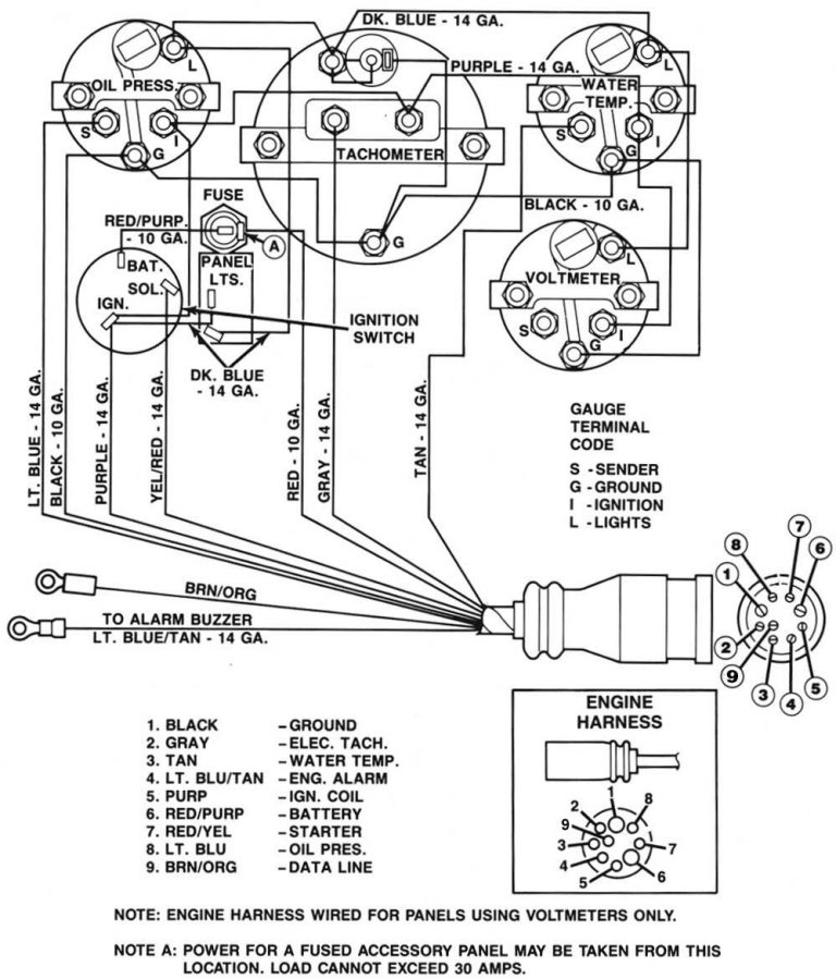
Photo Credit by: bing.com / mercruiser outboard inboard connector ignition volvo tach tachometer penta offshoreonly crusader sunpro 3000gt camaro imageservice teleflex beta outdrive seay gauges
Mercury Outboard Wiring Harness Diagram - Wiring Diagram
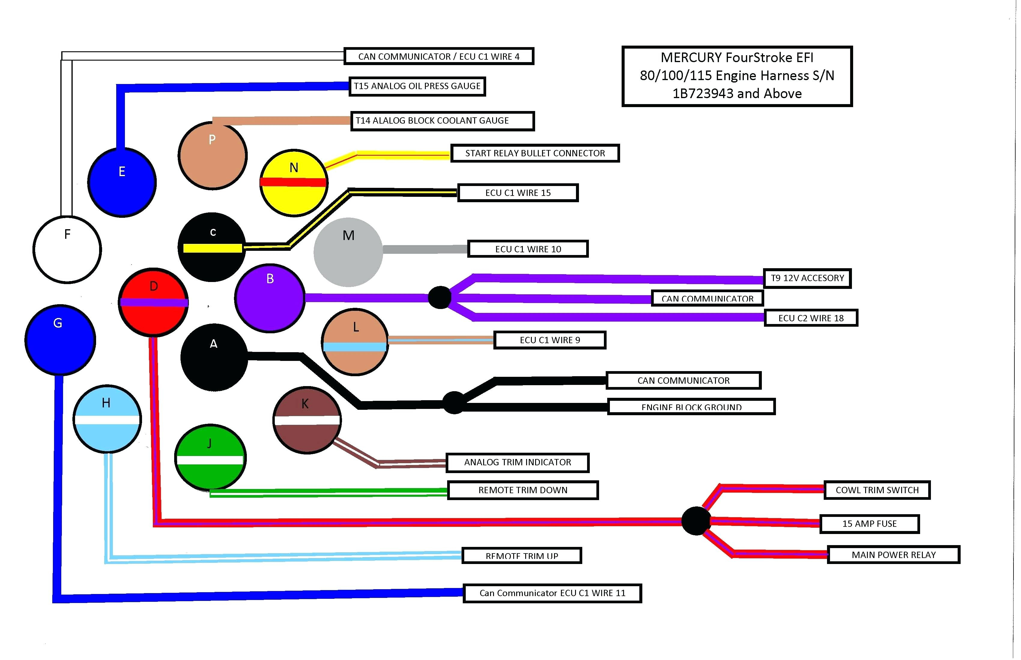
Photo Credit by: bing.com / outboard codes 2020cadillac capacitor harnes acronyms diagramtemplate diagramsample servisi
Mercury Tilt And Trim Gauge Wiring Diagram - Wiring Diagram
Photo Credit by: bing.com / wiring diagram trim gauge tilt mercury version quality hd
Mercury Tilt And Trim Gauge Wiring Diagram - Wiring Diagram

Photo Credit by: bing.com /
Mercury 8 Pin Wiring Diagram
Photo Credit by: bing.com /
Boat Gauge Wiring Diagram For Tachometer | Fuse Box And Wiring Diagram

Photo Credit by: bing.com / tachometer outboard faria gauges tach synchronizer tachometers imageservice mercruiser schematron readingrat evinrude schematics vdo electrical schemas wrg 1822 stickerdeals
Wiring Diagram For Mercury Outboard Motor - Free Wiring Diagram

Photo Credit by: bing.com / wiring diagram outboard mercury ignition switch johnson boat motor lawn suzuki mower tachometer kill marine hp wire key murray diagrams

