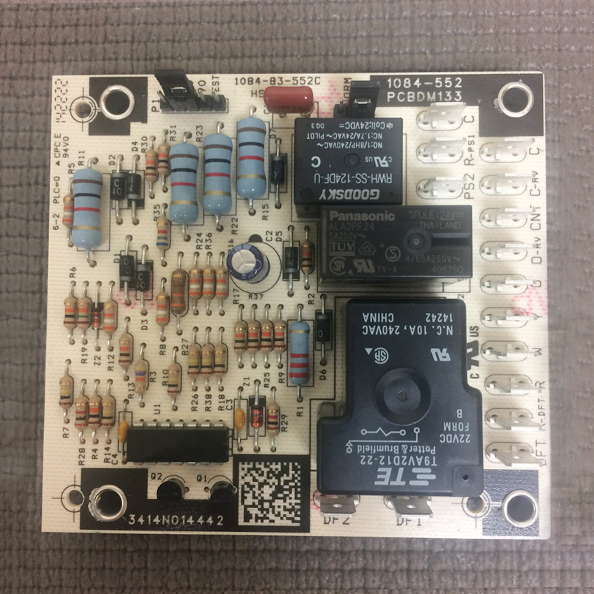
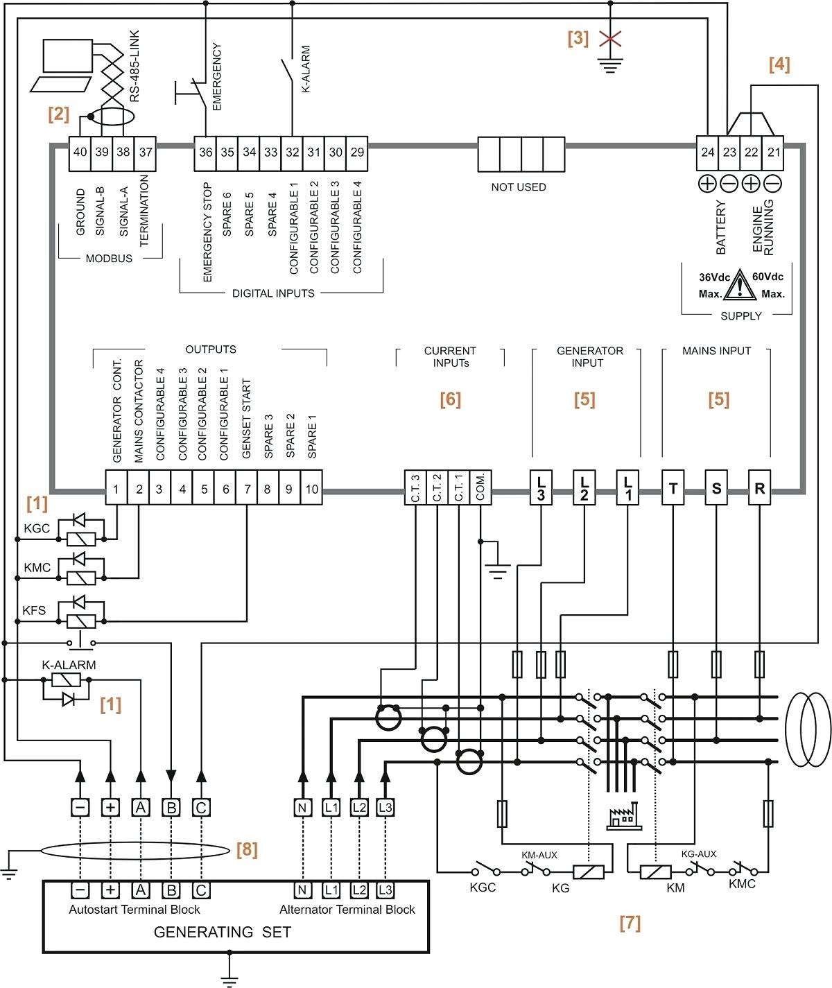
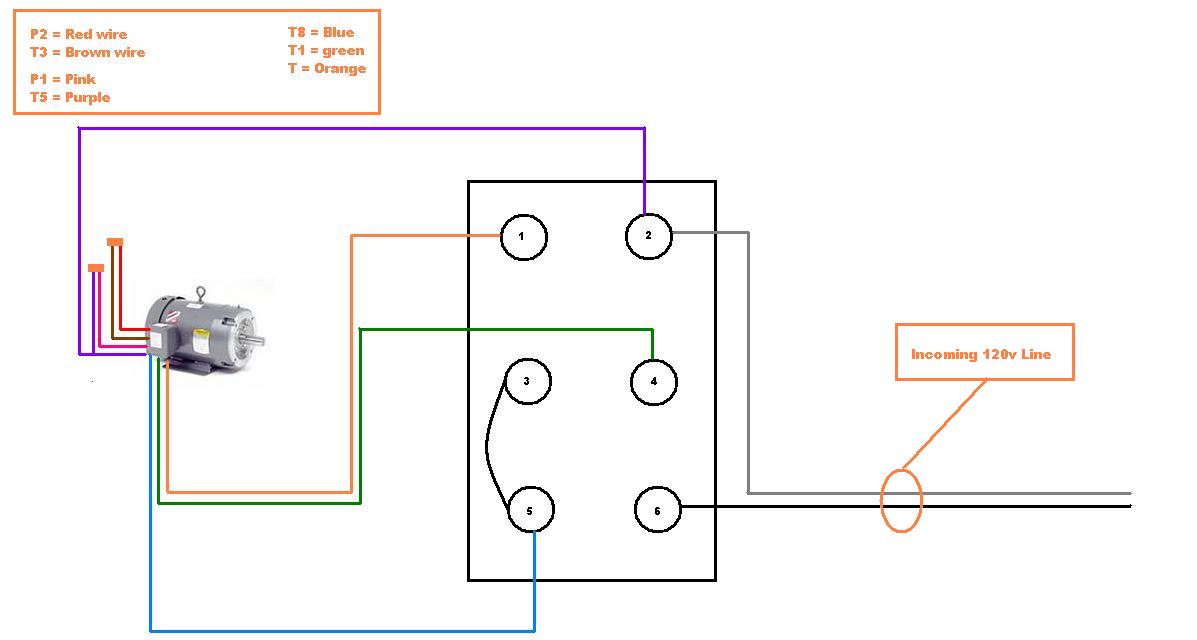
Pcbdm133 defrost control board wiring diagram
Table of Contents
Table of Contents
Do you know what Pcbdm133 Defrost Control Board Wiring Diagram is? If not, then you are missing out on a crucial component that is integral to the effective functioning of your heating and cooling system. This small piece plays a significant role in regulating the temperature and defrosting your HVAC system, and its importance cannot be overstated.
Issues with Pcbdm133 Defrost Control Board Wiring Diagram
Have you ever experienced issues with your heating and cooling system? Maybe the system is not functioning as expected, or it is taking longer to defrost. These and other issues may be related to Pcbdm133 Defrost Control Board Wiring Diagram. The circuit board regulates the defrost cycle of the system, but if it is not working correctly, then your system will not function as intended.
Target of Pcbdm133 Defrost Control Board Wiring Diagram
The key target of Pcbdm133 Defrost Control Board Wiring Diagram is to regulate the temperature and defrost cycles of your heating and cooling system. In essence, the board is responsible for determining when the system should defrost and how long the defrost cycle should take. These functions are essential to ensure optimal performance of the HVAC system.
Summary of Main Points
Pcbdm133 Defrost Control Board Wiring Diagram is an essential component of your heating and cooling system. Issues related to the board can lead to malfunctioning of your system. The primary target of the board is to regulate the temperature and defrost cycles of your HVAC system to ensure optimal performance.
How Pcbdm133 Defrost Control Board Wiring Diagram Works
When the temperature in the heat pump’s indoor coil goes below freezing point, the Pcbdm133 Defrost Control Board Wiring Diagram sends a signal to start the defrost cycle. The defrost cycle involves running the outdoor fan in the opposite direction for specified minutes to thaw the coil. Once the coil temperature has reached the desired range, the board will terminate the defrost cycle and return to normal operation. The board continually monitors the system to ensure that the temperature and defrost cycles are within acceptable limits.
The Importance of Pcbdm133 Defrost Control Board Wiring Diagram
The Pcbdm133 Defrost Control Board Wiring Diagram is vital to the proper functioning of your heating and cooling system. The board ensures that your system is operating optimally by regulating the temperature and defrost cycles. Without the board, your system could experience performance issues and malfunction, leading to costly repairs.
Common Issues With Pcbdm133 Defrost Control Board Wiring Diagram
One common problem with Pcbdm133 Defrost Control Board Wiring Diagram is damaged components, causing it to malfunction. This issue can be caused by power surges or electrical interference from other devices. Another problem is incorrect installation, which can damage the system, resulting in an expensive repair bill. Routine maintenance and inspections can help prevent these issues before they cause significant damage.
Personal Experience with Pcbdm133 Defrost Control Board Wiring Diagram
One winter, my HVAC system stopped working correctly, and it took longer to defrost. I called in a technician, and they diagnosed the problem as a faulty Pcbdm133 Defrost Control Board Wiring Diagram. The technician replaced the board, and my heating and cooling system started functioning correctly. The experience taught me the important role played by the board in the proper functioning of the heating and cooling system.
Frequently Asked Questions About Pcbdm133 Defrost Control Board Wiring Diagram
Q: How do I know if my Pcbdm133 Defrost Control Board Wiring Diagram is faulty?
A: A malfunctioning board may cause your heating and cooling system to operate erratically, taking longer to defrost, or not defrosting altogether. Calling a professional to diagnose the issue is recommended.
Q: How often should I have my Pcbdm133 Defrost Control Board Wiring Diagram checked?
A: Routine maintenance and inspection of your heating and cooling system, including the board, once a year is highly recommended. This maintenance can help prevent system failure and keep your system operating optimally.
Q: What happens if my Pcbdm133 Defrost Control Board Wiring Diagram fails?
A: A faulty board can cause your heating and cooling system to malfunction, leading to costly repairs. Calling a professional to inspect and replace the board as needed is highly recommended.
Q: How long does it take to replace a Pcbdm133 Defrost Control Board Wiring Diagram?
A: The time it takes to replace the board depends on the complexity of the system and how easily accessible the board is. Generally, a professional can replace the board within an hour or two.
Conclusion of Pcbdm133 Defrost Control Board Wiring Diagram
The Pcbdm133 Defrost Control Board Wiring Diagram is a crucial component of your heating and cooling system, regulating temperature and defrost cycles to ensure optimal performance. Routine maintenance and inspections can prevent expensive repairs and keep your system operating correctly.
Gallery
Pcbdm133 Defrost Control Board Wiring Diagram - Creativeal
Photo Credit by: bing.com /
PCBDM133 PCBDM133S Goodman Amana Janitrol Heat Pump Defrost Control

Photo Credit by: bing.com / janitrol amana goodman
Goodman Wiring Diagram Pcbdm133
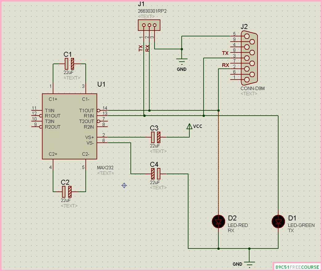
Photo Credit by: bing.com / wiring diagram goodman board 89c51 max232 reset course
Circuit Board – PCBDM133S / PCBDM160S Defrost Control Board – Goodman
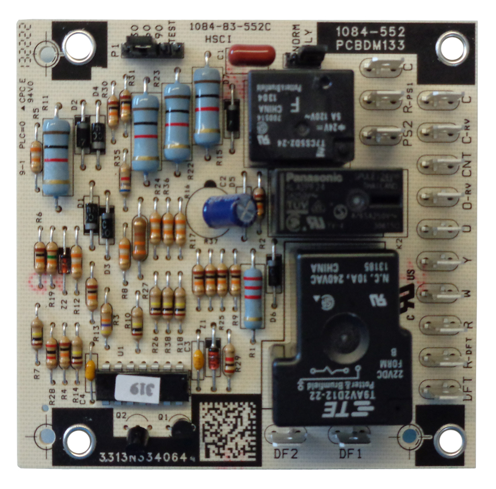
Photo Credit by: bing.com / board goodman control defrost circuit parts amana boards part sensor hvac heat partsaps air janitrol upvote furnace repair doityourself
Rheem Wiring Diagram - Wiring Schematica
Photo Credit by: bing.com /
Defrost Control Board Heat Pump Wiring - Universal Defrost Control For

Photo Credit by: bing.com / defrost goodman condensing communicating pump
Pcbdm133 Defrost Control Board Wiring Diagram - Creativeal
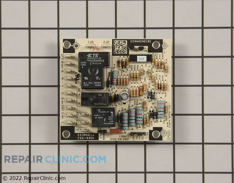
Photo Credit by: bing.com /
Goodman Defrost Board Wiring Diagram - Inspirenetic
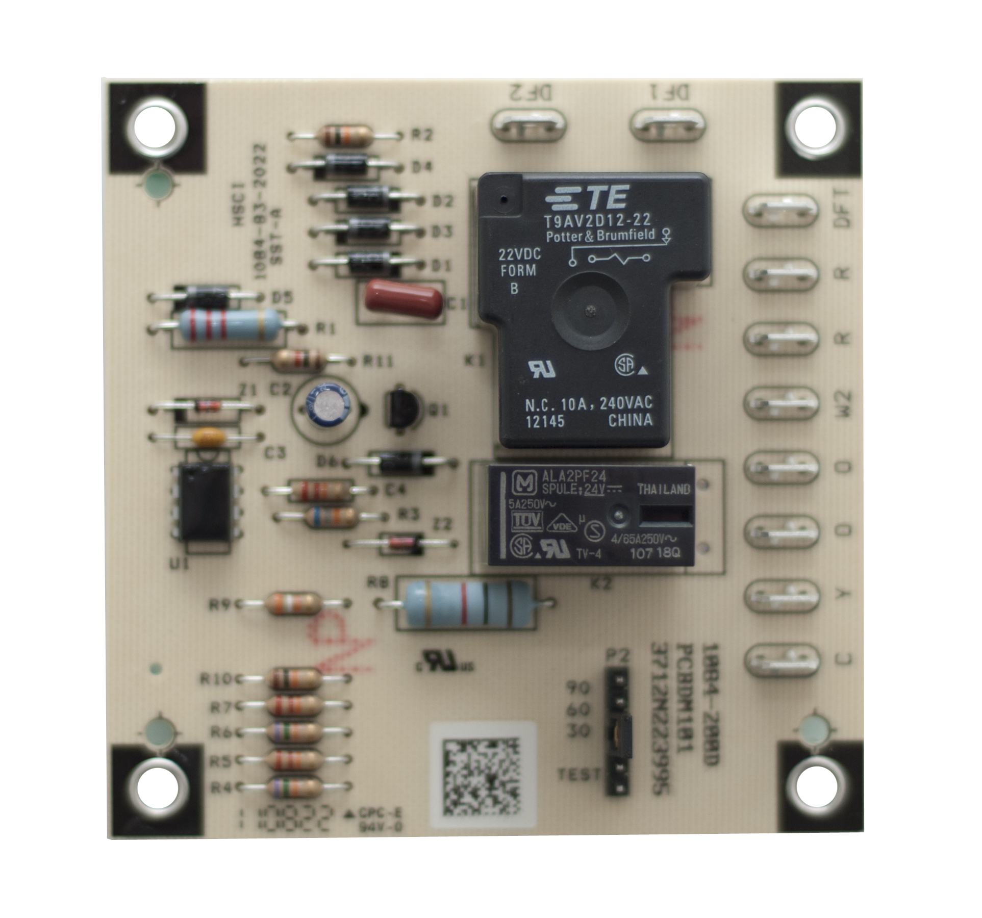
Photo Credit by: bing.com /
Directed 535t Wiring Diagram - Diy Hut

Photo Credit by: bing.com /
Pcbdm133 Defrost Control Board Wiring Diagram - Creativeal

Photo Credit by: bing.com /

