Peco wiring pl points led
Table of Contents
Table of Contents
Are you struggling to understand Peco Point Wiring Diagrams? Do you have a model railway system that requires you to use Peco Points, but you’re unsure of how to wire them correctly? If so, keep reading to learn everything you need to know about Peco Point Wiring Diagrams.
The Pain Points of Peco Point Wiring Diagrams
Model railway enthusiasts often struggle with wiring their Peco Points correctly. This can be due to a lack of understanding of the wiring diagrams or a lack of experience with electrical systems. Incorrect wiring can result in your trains not running smoothly or, worse yet, not running at all.
The Target of Peco Point Wiring Diagrams
The target of Peco Point Wiring Diagrams is to provide model railway enthusiasts with a clear understanding of how to wire their Peco Points correctly. By following the wiring diagrams, you can ensure that your trains run smoothly and that your model railway system is fully operational.
Summary of the Main Points
The key to success with Peco Point Wiring Diagrams is to follow the diagrams closely and seek expert advice and guidance if necessary. Understanding the diagrams will help ensure that your trains run smoothly, and that your model railway system operates at its best.
What is Peco Point Wiring Diagram?
Peco Point Wiring Diagrams illustrate how to wire Peco Points correctly to ensure that the trains run smoothly. As a model railway enthusiast, I used a Peco Point Wiring Diagram to ensure my system worked to the best of its ability.
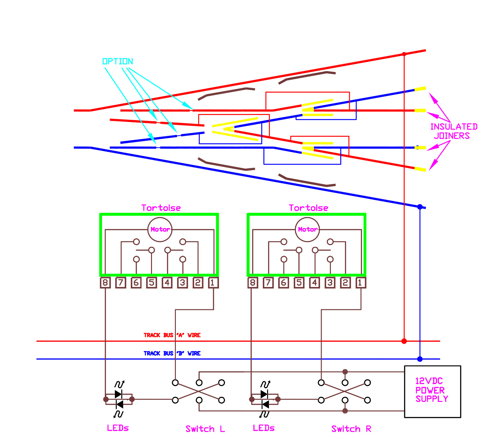 The diagram clearly shows how to wire the Peco Points, and if followed correctly, the user will have a fully operational model railway system.
Benefits of Peco Point Wiring Diagram
Using Peco Point Wiring Diagrams makes it easy for model railway enthusiasts to understand and wire their systems correctly. This can save time, money, and frustration with incorrect wiring. The diagrams allow users to see the correct wiring connections and ensure a smooth-running system.
.gif)Tips for Using Peco Point Wiring Diagrams
The most important tip when using Peco Point Wiring Diagrams is to follow the wiring diagrams closely and seek expert advice and guidance if needed. Additionally, ensure that all wiring connections are secure and correctly connected. Finally, before turning your system on, double-check all wiring connections to ensure there are no loose connections.
Understanding Insulfrog Vs. Electrofrog
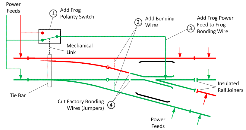
When using Peco Points, it’s essential to understand the difference between Insulfrog and Electrofrog. Insulfrog points have built-in insulation, whereas Electrofrog points require the user to use additional wiring for section isolation. This is important to understand when wiring Peco Points using Peco Point Wiring Diagrams.
 #### Using Track Feeders
Track feeders are essential when wiring Peco Points. These feeders provide power to the trains and are wired into the track bus wires. They are also necessary for Electrofrog points, as they support section isolation. When using Peco Point Wiring Diagrams, track feeders must be included in the wiring connections.
Question and Answer Section
Q: What is the difference between Insulfrog and Electrofrog?
A: Insulfrog points have built-in insulation, whereas Electrofrog points require the user to use additional wiring for section isolation.
Q: Why is it essential to understand Insulfrog Vs. Electrofrog?
A: When wiring Peco Points, it is important to know which type of point you are using to ensure that the wiring is done correctly and your trains will run smoothly.
Q: What is a track feeder?
A: A track feeder is a wire that provides power to trains and is wired into the track bus wires. They are especially important when using Electrofrog points, as they support section isolation.
Q: Why is it important to follow the wiring diagram?
A: Following the wiring diagram ensures that your trains run smoothly, your models remain operational, and your electrical system functions correctly.
Conclusion of Peco Point Wiring Diagrams
Understanding Peco Point Wiring Diagrams is crucial to the success of your model railway system. By following the diagrams closely and using expert advice and guidance, you can wire your Peco Points effectively and have a fully operational system that runs smoothly.
Gallery
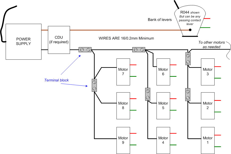
Wiring Diagram For Peco Point Motors
.gif)
Photo Credit by: bing.com / peco relays
Wiring Diagrams
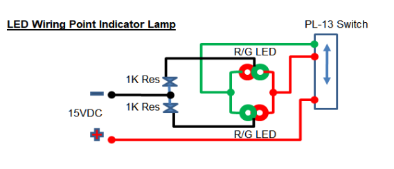
Photo Credit by: bing.com / peco wiring pl points led
PL-15 Peco Twin Micro Switch Kit For Fitling To Turnout Motor PL-10

Photo Credit by: bing.com / peco pl motor switch turnout micro twin point kit fitting 10e accessory 13 model electrics digital osbornsmodels footplate
Tortoise Point Motor Wiring Diagram - Wiring Diagram

Photo Credit by: bing.com / peco insulfrog electrofrog dcc
Hattons.co.uk - Peco Products PL-34 Pre-wired Wiring Loom For Use With

Photo Credit by: bing.com / pl wiring motors peco 10e diagram wired loom pre use hattons
Modifying Peco Points For DCC

Photo Credit by: bing.com / peco points dcc turnouts diagram point switch wire layout giphy microswitch gif into small lever underside path modifying ozsite au
Electrical Page 2
.gif)
Photo Credit by: bing.com / peco lever pl26 wiring point motors pl11 hornby cdu contact pm20 passing lambert brian gaugemaster surface using operation
Peco Pl11 Wiring Diagram - Updiary

Photo Credit by: bing.com /
Peco Lectrics

Photo Credit by: bing.com / peco pl switch lectrics points turnout module osbornsmodels
Wiring Diagram For Peco Point Motors - Wiring Draw And Schematic

Photo Credit by: bing.com /
