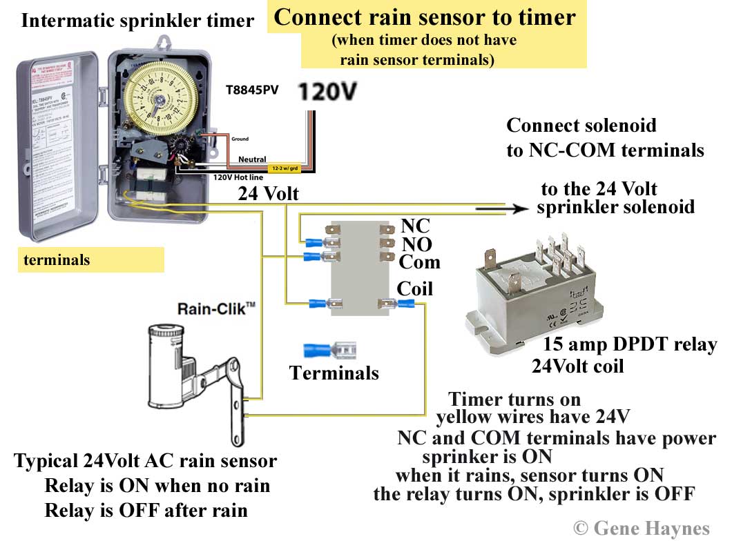
Intermatic wiring diagram sprinkler timer rain connect sensor wire timers relay irrigation work does clock terminals install tr trying while
Table of Contents
Table of Contents
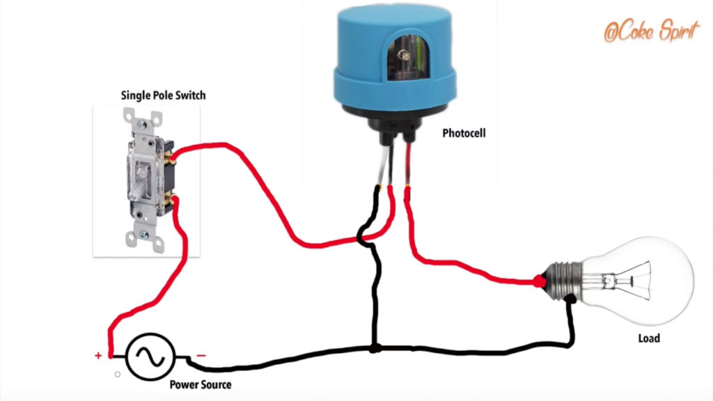
Do you want to save energy and reduce your electricity bill? If so, you may want to consider installing a photocell timer contactor wiring diagram. This system automatically turns your lights on at dusk and off at dawn, saving you money and energy. Keep reading to learn more about Photocell Timer Contactor Wiring Diagram and how it works.
The Pain Points with Lighting Systems
Many people feel that lighting systems can be complicated and expensive to install. Additionally, they often require regular maintenance and adjustments to ensure that they are working properly. This can be frustrating and time-consuming, especially if you need to climb up a ladder or go into a dark basement to fix the problem.
The Target of Photocell Timer Contactor Wiring Diagram
A photocell timer contactor wiring diagram is designed to address these pain points by automating the process of turning your lights on and off. This system uses a photocell sensor that detects the levels of ambient light, turning on your lights when it gets dark and turning them off when it gets light again, saving you time, money, and energy.
Main Points about Photocell Timer Contactor Wiring Diagram
A photocell timer contactor wiring diagram can be installed in homes or businesses, and it can be used for both indoor and outdoor lighting. This system is easy to install and requires minimal maintenance. It can also be customized to suit your needs, allowing you to set specific times and hours for your lights to turn on and off. By using a photocell sensor, this system is incredibly accurate and reliable.
The Target of Photocell Timer Contactor Wiring Diagram and More Explanation
If you’re interested in installing a photocell timer contactor wiring diagram, you may be wondering how it works. Essentially, the system consists of four main components: the photocell sensor, the timer, the contactor, and the wire. The photocell sensor detects changes in ambient light, and sends a signal to the timer. The timer then turns on the contactor, which supplies power to the lights. When the ambient light reaches a certain level, the photocell sensor sends another signal to the timer, which turns off the contactor, and your lights turn off. By using this system, you can reduce your energy consumption, save money on your electricity bill, and even extend the life of your light bulbs.
FAQs About Photocell Timer Contactor Wiring Diagram
1. What are the benefits of installing a photocell timer contactor wiring diagram?
A: Installing a photocell timer contactor wiring diagram can save you money on your electricity bill, reduce your energy consumption, and extend the life of your light bulbs. It can also be customized to suit your needs, allowing you to set specific times and hours for your lights to turn on and off.
2. Can a photocell timer contactor wiring diagram be installed in both homes and businesses?
A: Yes, a photocell timer contactor wiring diagram can be installed in both homes and businesses, and it can be used for both indoor and outdoor lighting.
3. How accurate and reliable is a photocell timer contactor wiring diagram?
A: By using a photocell sensor, a photocell timer contactor wiring diagram is incredibly accurate and reliable. You can be sure that your lights will turn on and off exactly when you need them to.
4. Does a photocell timer contactor wiring diagram require regular maintenance?
A: No, a photocell timer contactor wiring diagram requires minimal maintenance. Once installed, it will work automatically without requiring any additional adjustments or tweaks.
Conclusion of Photocell Timer Contactor Wiring Diagram
If you’re tired of dealing with complicated and expensive lighting systems, a photocell timer contactor wiring diagram may be the solution you’re looking for. By automating the process of turning your lights on and off, you can save time, money, and energy, and enjoy a more convenient and hassle-free lighting experience.
Gallery
Contactor And Photocell Wiring Diagram

Photo Credit by: bing.com / photocell contactor wiring refer
How To Wire A Photocell With A Relay Contactor For Outsiden
Photo Credit by: bing.com / photocell contactor wire relay wiring lighting circuit further need hesitate ask please if assistance helps hope
Photocell Lighting Contactor Wiring Diagram | Elec Eng World

Photo Credit by: bing.com / photocell wiring diagram contactor lighting timer wire electrical engineering eng lưu đã từ expand lights ambrasta
Photocell Wiring Diagram - Wiring Diagram

Photo Credit by: bing.com / photocell diagram wiring circuit wire photoelectric switch light sensor hook override control power wires connections together
240v Photocell Wiring Diagram

Photo Credit by: bing.com / wiring diagram photocell 240v intermatic contactor cell pump pool lighting
Intermatic T104r Wiring Diagram

Photo Credit by: bing.com / intermatic wiring diagram sprinkler timer rain connect sensor wire timers relay irrigation work does clock terminals install tr trying while
40 Photocell Wiring Diagram Pdf West Virginia

Photo Credit by: bing.com /
Wiring Diagram For 208 Volt Photocell - Wiring Diagram

Photo Credit by: bing.com / wiring photocell contactor justanswer halide
Photocell Sensor Connection With A Contactor - YouTube

Photo Credit by: bing.com / photocell contactor connection
Photocell Wiring With Contactor | Diagram, Electricity, Wire

Photo Credit by: bing.com / photocell wiring contactor diagram sensor light lighting dusk dawn switch tankbig wire photoelectric


