Controller pid temperature box control wiring diagram ssr heating controllers cost low
Table of Contents
Table of Contents
Pid Temperature Controller Wiring Diagram is an essential element for anyone who wants to maintain a constant temperature for their projects, whether it be in the cooking or manufacturing industry. This article aims to guide you through the importance of Pid Temperature Controller Wiring Diagram and how it can benefit you in your day-to-day life.
Pain Points of Pid Temperature Controller Wiring Diagram
Without employing Pid Temperature Controller Wiring Diagram, it can be challenging to maintain the required temperature for your project. A fluctuation of just one degree Celsius or Fahrenheit can cause your project to fail, affecting your time, money, and quality of work. Besides, a lack of knowledge of Pid Temperature Controller Wiring Diagram can make it challenging to set up the entire system correctly, leading to frustration and wasted time.
What is the Target of Pid Temperature Controller Wiring Diagram?
The main goal of Pid Temperature Controller Wiring Diagram is to ensure that the temperature remains constant to avoid any deviations that may affect the project’s outcome. This is achieved by monitoring the temperature and adjusting heat sources, such as heaters or coolers, as required, keeping the temperature at the desired level. The process includes a feedback mechanism that controls the output of the heat sources to ensure precision and stability.
Summary of Pid Temperature Controller Wiring Diagram
Pid Temperature Controller Wiring Diagram is a crucial element for maintaining a consistent temperature, and its application is widely used in various industries, such as cooking, manufacturing, and agriculture. This article has touched on the importance of Pid Temperature Controller Wiring Diagram, its target, and the pain points of not using it. Let us delve deeper into this topic and explore the different aspects of Pid Temperature Controller Wiring Diagram.
Understanding Pid Temperature Controller Wiring Diagram
Pid Temperature Controller Wiring Diagram is an engineering technique that employs a closed-loop control system. This system constantly monitors the temperature through a sensor and compares it to the reference temperature set by the user. If there is a temperature deviation, the controller adjusts the heat sources accordingly.
Using Pid Temperature Controller Wiring Diagram, you can control various attributes of the system, such as setpoint, gain, and deadband, ensuring that the system can adapt to variations in temperature, particularly during start-up and load changes.
Setting up the Pid Temperature Controller Wiring Diagram
Before setting up the Pid Temperature Controller Wiring Diagram system, you need to identify several components, such as thermocouples, heater, controller, and power source. Once all the components are identified, you can commence the wiring process. The wiring process must conform to the wiring diagram that is specific to your temperature controller. It is vital to follow the wiring diagram to ensure that the system operates correctly.
A Note on Safety
Pid Temperature Controller Wiring Diagram involves working with electricity. It is vital to ensure the safety of the people involved in the wiring process. When working with electricity, always switch off the power source before starting the wiring process. Also, wear suitable protective gear while handling the wires.
Maintenance of Pid Temperature Controller Wiring Diagram
Maintenance of Pid Temperature Controller Wiring Diagram is crucial to ensure that the system continues to function correctly. It is essential to inspect the wires regularly and replace any worn-out parts to avoid system failures. Also, periodically check the setpoint temperature to ensure that it is accurate and make any necessary adjustments as required.
Question and Answer
Q1. What are the different types of Pid Temperature Controller Wiring Diagram?
A1. The different types of Pid Temperature Controller Wiring Diagram include Proportional Integral Derivative (PID), On-Off, and floating.
Q2. How do you determine the heat source required for Pid Temperature Controller Wiring Diagram?
A2. The heat source required for Pid Temperature Controller Wiring Diagram depends on the nature of the project. A heater is used to increase temperature, while a cooler is used to decrease temperature.
Q3. Can you use Pid Temperature Controller Wiring Diagram for solar heating systems?
A3. Yes, Pid Temperature Controller Wiring Diagram can be used for solar heating systems to maintain a constant temperature.
Q4. What are the ideal applications of Pid Temperature Controller Wiring Diagram?
A4. Pid Temperature Controller Wiring Diagram is widely used in the cooking, manufacturing, and agriculture industries to maintain precise and consistent temperatures.
Conclusion of Pid Temperature Controller Wiring Diagram
Pid Temperature Controller Wiring Diagram is an excellent tool for maintaining a constant temperature in various projects. This article covered the essentials of Pid Temperature Controller Wiring Diagram, touching on its target, application, and pain points. It is essential to note that setting up Pid Temperature Controller Wiring Diagram requires expert knowledge and an understanding of wiring diagrams. We hope this article guides you in understanding Pid Temperature Controller Wiring Diagram and its benefits, allowing you to achieve your desired temperature in your projects.
Gallery
Solid State Relay - Connecting PID Controller To SSR - Electrical

Photo Credit by: bing.com / ssr pid wiring controller diagram relay solid temperature state connecting load heat input electrical sponsored links
Pid Temperature Controller Wiring Diagram
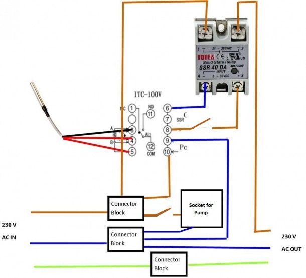
Photo Credit by: bing.com / wiring pid diagram controller temperature switch pump built pre so ll
Pid Temperature Controller Wiring Diagram - The Sands Mechanical Museum
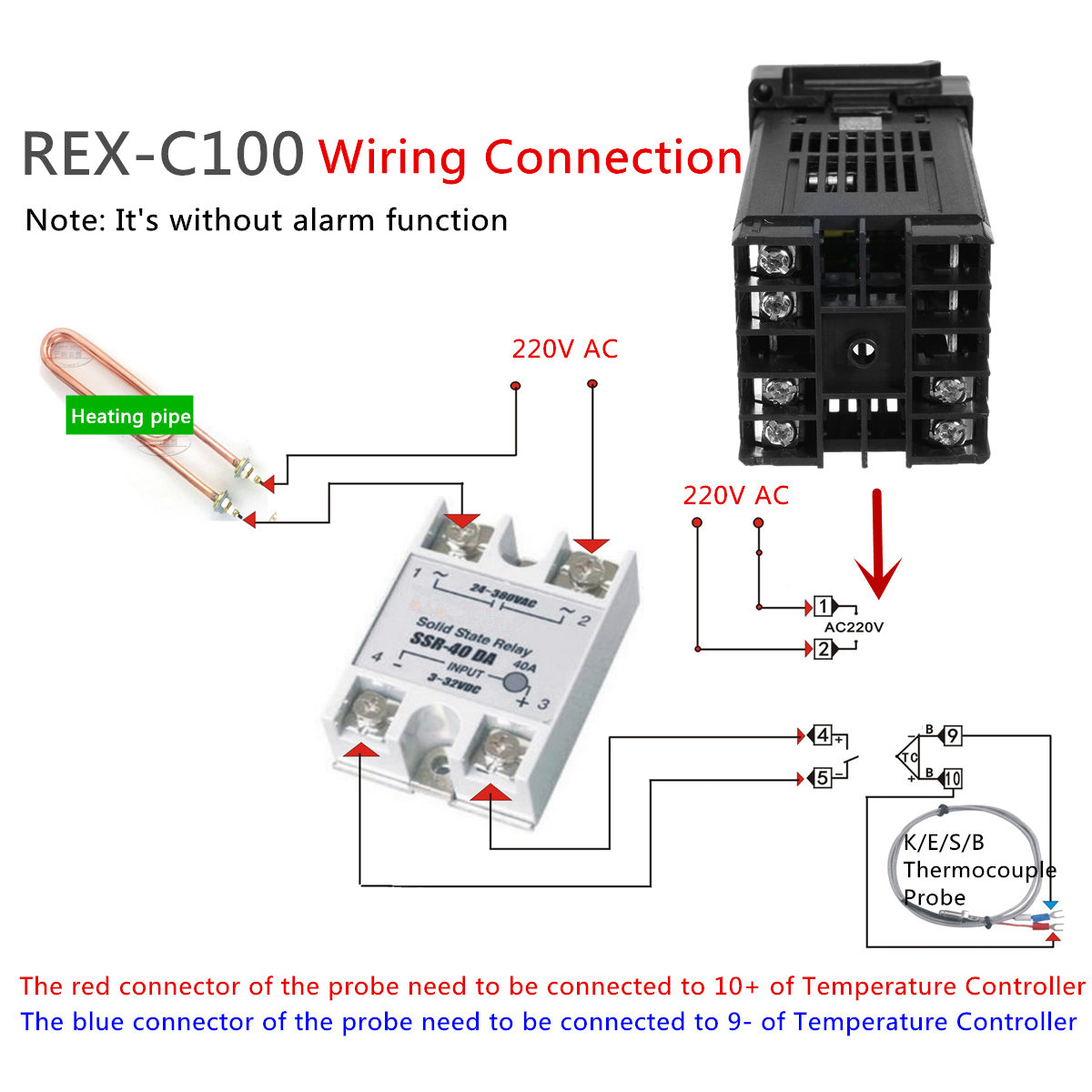
Photo Credit by: bing.com / rex temperature c100 ssr controlador 220v thermocouple staticbg imgaz 60hz 40a posting cooling controllers
Pid Temperature Controller Wiring Diagram - Free Wiring Diagram

Photo Credit by: bing.com / pid temperature controller diagram arduino wiring goal projects hold wordpress
Temperature Controller Wiring Diagram / Amazon Com Elitech Stc 1000

Photo Credit by: bing.com / pid diagram ssr c100 makezine element anr bladesmithsforum stc controllers elitech
Pid Temperature Controller Wiring Diagram - Wiring Diagram Source
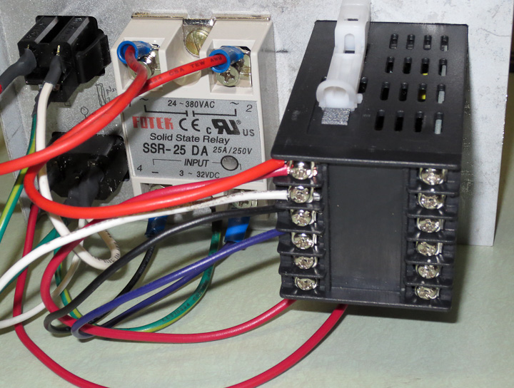
Photo Credit by: bing.com / controller pid temperature box control wiring diagram ssr heating controllers cost low
Pid Temperature Controller Wiring Diagram - Diagram Resource Gallery
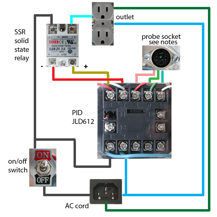
Photo Credit by: bing.com / diagram
Pid Temperature Controller Wiring Diagram - Diy Stc 1000 2 Stage

Photo Credit by: bing.com / temperature
Pid Temperature Controller Wiring Diagram / How To Control Temperature

Photo Credit by: bing.com / pid
Build Your Own Digital Forced Draft Smoker Controller - UK BBQ Review
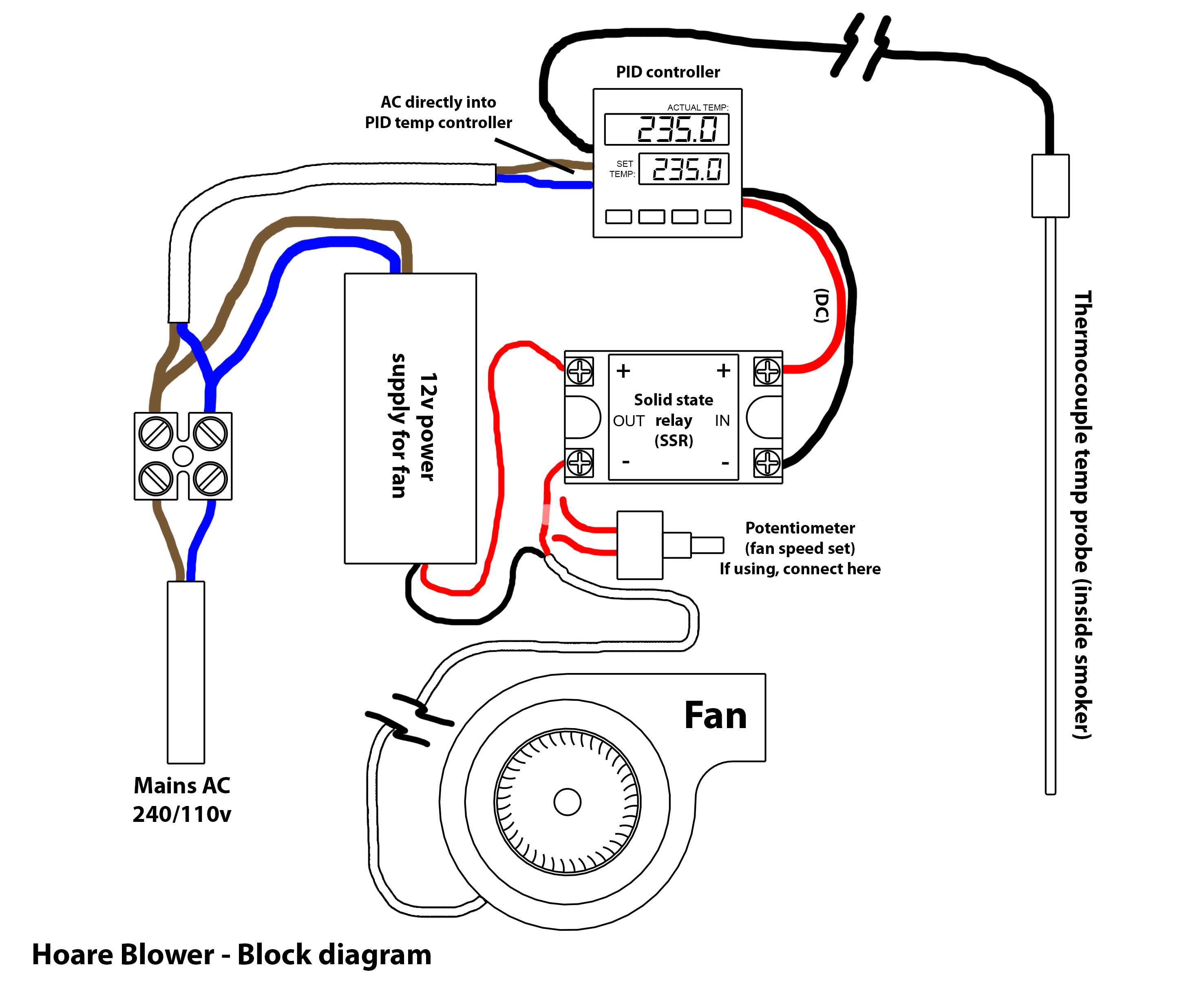
Photo Credit by: bing.com / smoker controller draft pid forced build digital bbq diagram own control power


