Generator wiring diagram manual switch changeover transfer electrical portable circuit house connect schematics electricalonline4u diagrams electric switches supply panel outlet
Table of Contents
Table of Contents
Rotary Changeover Switch Wiring Diagram is a crucial element in any electrical installation. It plays a significant role in transferring the load from one source to another in the event of a power outage or other electrical faults. In this blog post, we will discuss Rotary Changeover Switch Wiring Diagram, its importance, and how it works.
Pain Points
Rotary Changeover Switch Wiring Diagram can be a complex process without proper guidance, and improper installation can lead to malfunctioning of the switch and ultimately affect the entire electrical system. It requires extreme precision to ensure that the switch operates as expected in case of a power failure.
Target of Rotary Changeover Switch Wiring Diagram
The main objective of the Rotary Changeover Switch is to transfer the electrical load from the primary source to an alternate source efficiently during power outages or other electrical issues. It is a reliable mechanism that ensures the continuity of power supply to critical electrical appliances in a building or facility.
Summary
Rotary Changeover Switch Wiring Diagram is a crucial element in electrical installations, ensuring the smooth transfer of the electrical load from primary to secondary sources. Proper installation and maintenance of the switch are essential to ensure its longevity and prevent any system malfunctioning. In the following paragraphs, we will delve deeper into the topic of Rotary Changeover Switch Wiring Diagram.
Understanding Rotary Changeover Switch Wiring Diagram
The Rotary Changeover Switch works as a switching mechanism activated by a rotary cam. The cam moves between two positions; when the cam is at one end, the switch transfers power from the primary source, and when it rotates, the switch transfers power from the secondary source.
My experience with the Rotary Changeover Switch Wiring Diagram involved a building with a solar panel system for generating electricity. The switch made it possible to switch between the primary electrical grid and the solar panel system quickly. Properly installing the switch was crucial to ensure that the two power sources did not interfere with each other.
The wiring diagram for the Rotary Changeover Switch includes three sections: the rotary switch, the load, and the power sources. The three sections are connected to ensure the switch transfers power from the primary source to the load and vice versa. The wiring should be done accurately, and the connections should be tight to prevent any disconnections.
Installation of Rotary Changeover Switch Wiring Diagram
The first step in the installation of the Rotary Changeover Switch is selecting the appropriate switch for the load required. The switch should be of a durable material and insulated against the environment. The switch’s installation should be done by an experienced electrician to ensure it’s correctly installed based on the manufacturer’s instructions.
The installation of the switch begins with the inspection of the system to ensure it’s compatible with the switch. After verifying, the installation process involves attaching the wires to the switch and testing the switch for effective transfer of power between the primary and secondary sources.
Maintenance of Rotary Changeover Switch Wiring Diagram
Proper maintenance is essential to ensure the switch’s longevity and prevent any malfunctioning, which could cause system damage. Frequent inspection is necessary to verify that the connections are intact and check for any signs of wear or corrosion. If any of these issues arise, the switch should be replaced to avoid any potential risks.
Conclusion of Rotary Changeover Switch Wiring Diagram
Rotary Changeover Switch Wiring Diagram is a complex process that involves connecting three sections of the system and ensuring the smooth transfer of power between them. Selecting a durable switch, proper installation, and maintenance are crucial in ensuring the switch’s longevity and reliability in case of power outages or other electrical faults.
Question and Answer
Q: Why is it essential to use a durable and insulated switch for the Rotary Changeover Switch?
A: A durable and insulated switch is necessary as it ensures the switch’s longevity and the safety of the entire electrical system. It protects the switch from environmental factors such as temperature changes, corrosion, and abrasions that could cause electrical system malfunctions.
Q: How is the Rotary Changeover Switch activated?
A: The Rotary Changeover Switch is activated by a rotary cam that moves between the two positions, switching between the primary source and the secondary source as needed.
Q: Can the Rotary Changeover Switch be installed by anyone?
A: No, the installation of the Rotary Changeover Switch should only be done by an experienced electrician to ensure proper installation according to the manufacturer’s instructions.
Q: What is the importance of maintenance for the Rotary Changeover Switch?
A: Proper maintenance ensures the switch’s longevity and promotes efficient transfer of power in case of power outages or other electrical issues. It also prevents any potential safety risks to the entire electrical system.
Gallery
2 Pole Changeover Switch Wiring Diagram - 2 Pole Knife Switch 100A

Photo Credit by: bing.com / switch selector changeover 3800a c45 ammeter magnadyne imageservice atari 100a
Wiring Diagram Required For Rotary Cam Changeover Switch - Boat

Photo Credit by: bing.com / switch diagram wiring rotary selector cam changeover blue schematic required 120v electrical blueseas site
Rotary Changeover Switch Wiring Diagram - Rotary Cam Switch Changeover

Photo Credit by: bing.com / changeover wiring transfer
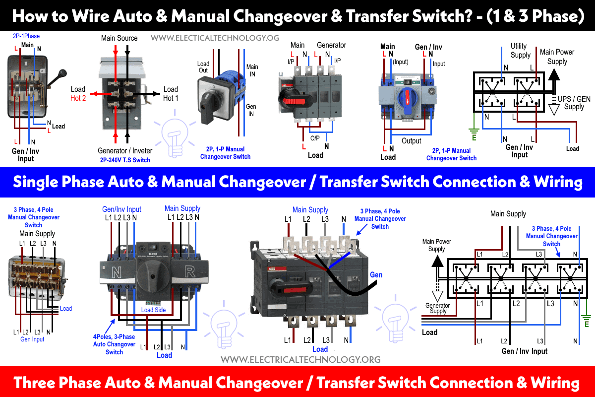
Wiring Auto & Manual Changeover / Transfer Switch - (1 & 3-Φ)

Photo Credit by: bing.com / switch changeover transfer manual phase wire automatic auto single three
3 Phase Manual Changeover Switch Wiring Diagram For Generator
Photo Credit by: bing.com / wiring changeover transfer
3 Phase Manual Change Over Switch Connection / Three Phase Manual

Photo Credit by: bing.com /
Rotary Changeover Switch Wiring Diagram - Rotary Cam Switch Changeover
Photo Credit by: bing.com / switch wiring changeover cam electrical
Manual Changeover Switch Wiring Diagram For Portable Generator

Photo Credit by: bing.com / generator wiring diagram manual switch changeover transfer electrical portable circuit house connect schematics electricalonline4u diagrams electric switches supply panel outlet
Wiring A Rotary Switch Brilliant Wiring Up An Ibanez, HH Setup To, Way

Photo Credit by: bing.com / rotary selector ibanez exceptional tonetastic magnificent
How To Control Two Meter In Rotary Change Over Switch Connection

Photo Credit by: bing.com / changeover rotary


