Capacitor start motor wiring diagram
Table of Contents
Table of Contents
The Single Phase Capacitor Start Capacitor Run Motor Wiring Diagram is a crucial aspect of electrical engineering, particularly for those who deal with small to medium-sized electric motors. If you are an electrician, a DIY enthusiast, or anyone dealing with motors, you must have come across this diagram at some point in your life. However, the concept can be quite overwhelming and challenging to understand, especially for beginners.
The Pain Points of Single Phase Capacitor Start Capacitor Run Motor Wiring Diagram
Many people often find the wiring diagram complicated and confusing, particularly when connecting all the necessary components. Following the right procedure is essential to avoid costly mistakes such as motor damage or electrical shock. Furthermore, some wiring diagrams may not be accurate or may require a specific understanding of electrical engineering terminology, which can make things even more challenging.
The Target of Single Phase Capacitor Start Capacitor Run Motor Wiring Diagram
The Single Phase Capacitor Start Capacitor Run Motor Wiring Diagram aims to show how to connect motor components by providing a visual representation of each connection’s order. The diagram aims to help electricians and engineers understand the correct sequence and connections for the motor to function without issues.
Summary of Single Phase Capacitor Start Capacitor Run Motor Wiring Diagram and Related Keywords
The Single Phase Capacitor Start Capacitor Run Motor Wiring Diagram demonstrates how to connect a single-phase induction motor’s capacitor to ensure a safe and efficient motor operation. The diagram displays the correct wire connections, including the capacitor, auxiliary winding, and the main winding. Electricians and engineers use the diagram to avoid motor burnouts and Electrical shorts in their electrical systems while also ensuring the motor runs at optimal speeds.
Understanding Single Phase Capacitor Start Capacitor Run Motor Wiring Diagram in Depth
Understanding the wiring diagram requires a broader understanding of the motor’s components and connections. A capacitor start capacitor run motor has a start winding, an auxiliary winding, and a run winding. The start and auxiliary windings are connected in parallel with the capacitor. When power is applied to the motor, the start winding energizes, producing a rotating magnetic field. This field interacts with the run winding, allowing the motor to initiate rotation. The capacitor stays energized until the motor reaches the predetermined operating speed. At this point, the auxiliary winding disengages, leaving the run winding as its only power source.
Understanding the motor’s internal connection diagram is crucial for proper motor operation to prevent damage to the electrical system. Carefully following the wiring diagram will save time and money while also avoiding accidents such as fires or electric shock.
Components Connected to Single Phase Capacitor Start Capacitor Run Motor
Several components are connected to Single Phase Capacitor Start Capacitor Run Motor to ensure proper operation. The component includes;
- The Main Power Supply
- Start Capacitor
- Auxiliary Winding
- Main Winding
- Overload Protection
Understanding how each of the components’ connections can help identify any issues with the motor’s electrical system quickly.
Other Important Considerations When Wiring Single Phase Capacitor Start Capacitor Run Motor
When wiring the motor, it’s essential to consider the wire gauge, insulation, and conductor type. The wire must be capable of handling the motor’s current needs and be covered with protective insulation to prevent electrical shock or fire hazards. Furthermore, it’s essential to choose the correct size of the capacitor and ensure it’s appropriately connected as per the wiring diagram. Failure to adhere to these guidelines may cause premature motor failure, leaving you with expensive repairs or replacement costs.
Why Choose Single Phase Capacitor Start Capacitor Run Motor
The Single Phase Capacitor Start Capacitor Run Motor is cost-effective and a practical option for low horsepower applications. They are efficient and more straightforward in design, making them ideal for single-phase applications in small industries or home appliances such as refrigerators, washing machines, and air conditioning systems. The use of a capacitor allows for a smooth start and the correct speed regulation, preventing the motor from consuming more power than necessary.
Question and Answer Section
Q1: What is the purpose of the Capacitor Start Capacitor Run Motor Wiring Diagram?
The primary goal of this diagram is to provide a visual representation of the proper connection sequence and order for connecting the motor components. The diagram aims to help electricians and engineers understand how to connect the motor’s capacitor correctly.
Q2: Why is following the wiring diagram critical?
Following the wiring diagram is essential to ensuring the motor operates correctly without causing any damage to the electrical system. Proper wiring protects the motor, preventing it from burning out or shorting out.
Q3: What components are connected to Single Phase Capacitor Start Capacitor Run Motor Wiring Diagram?
Several components are connected to Single Phase Capacitor Start Capacitor Run Motor to ensure proper operation. The component includes; the main power supply, start capacitor, auxiliary winding, main winding, and overload protection.
Q4: Can you run a dual capacitor motor on a single capacitor?
No, because the dual capacitor motor requires two capacitors with specific ratings to function properly. Running a dual capacitor motor on a single capacitor may result in motor failure and cause significant electrical problems in your system.
Conclusion of Single Phase Capacitor Start Capacitor Run Motor Wiring Diagram
The Single Phase Capacitor Start Capacitor Run Motor Wiring Diagram is essential to the electrical system as it provides a visual representation of the motor’s correct connections. Understanding the wiring diagram is crucial in preventing motor burnouts, electrical shorts or shocks while also ensuring the motor runs at optimal speeds. Following the wiring diagram closely saves time and money in the long run, providing safe and efficient motor operation.
Gallery
Types Of Single Phase Induction Motors | Single Phase Induction Motor
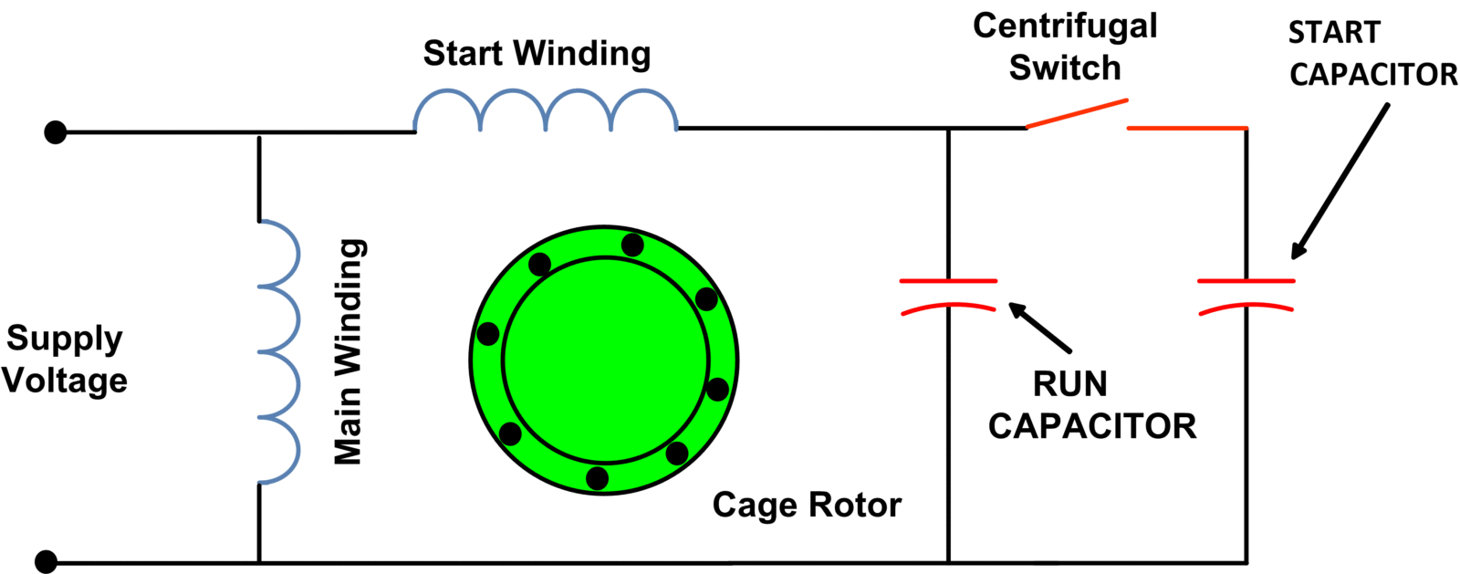
Photo Credit by: bing.com / capacitor start electricala2z seche linge condensateur hookup condenser blower remplacer branche technologie
Capacitor Start Capacitor Run Motor Circuit (wiring) Diagram And Torque

Photo Credit by: bing.com /
Single Phase Motor Wiring Connection | Capacitor | Urdu Hindi - YouTube

Photo Credit by: bing.com / phase motor wiring single capacitor connection
Capacitor Start Capacitor Run Motor Wiring Diagram - Wiring Diagram
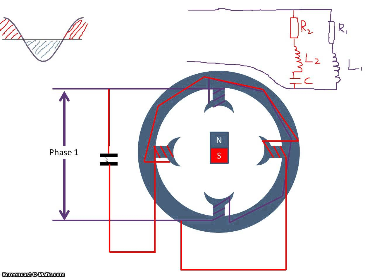
Photo Credit by: bing.com / motor capacitor diagram start run wiring phase single glamorous
230v Single Phase Capacitor Wiring Diagram Diagrams Schematics For

Photo Credit by: bing.com / 230v capacitor
Single Phase Capacitor Start And Capacitor Run Electric Motor Control-A
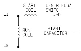
Photo Credit by: bing.com / capacitor phase start motor single circuit run electric diagram electrical control process capacitors basic schematic industrial automation technology guide two
Hyderabad Institute Of Electrical Engineers: Wiring Diagram Of A Single

Photo Credit by: bing.com / wiring phase motor single diagram capacitor switch start reverse winding l1 l2 run red direction two electrical neutral drum please
Single Phase Motor Wiring Diagram With Capacitor - Wiring Diagram
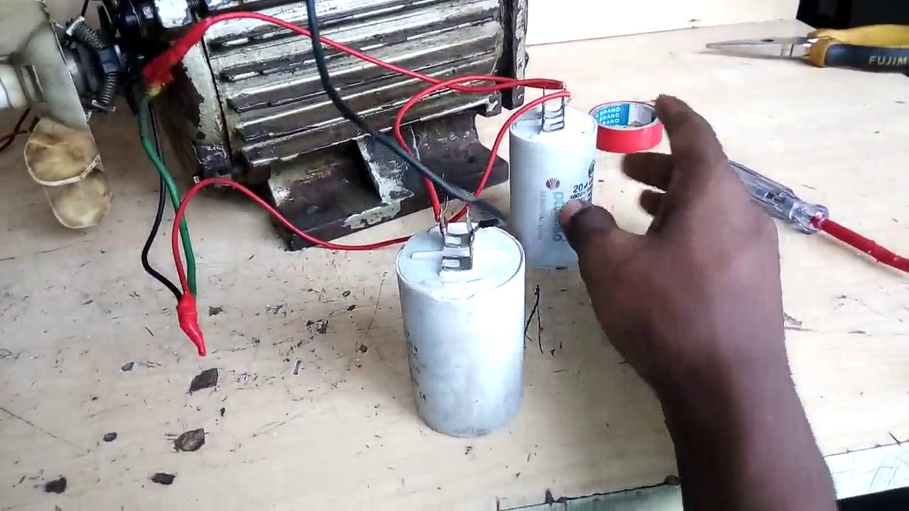
Photo Credit by: bing.com / capacitor baldor hubs
☑ How To Wire A Capacitor Start Electric Motor

Photo Credit by: bing.com / capacitor induction diagrams electric qzsi
Capacitor Start Motor Wiring Diagram - Cadician’s Blog

Photo Credit by: bing.com / capacitor wiring diagram motor start compressor wire ac 125v block untpikapps


