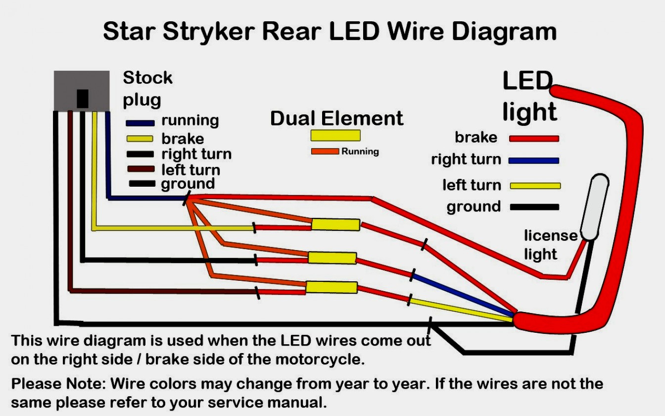
Solenoid valve wiring diagram
Table of Contents
Table of Contents
If you are in the manufacturing industry, you have likely heard about solenoid valve wiring diagrams. These diagrams are an essential aspect of the manufacturing process and are crucial for ensuring that your machinery and equipment work correctly. In this post, we will go in-depth about solenoid valve wiring diagrams, what they are, and why they are so important.
Pain Points Related to Solenoid Valve Wiring Diagram
Anyone who has worked in manufacturing understands that there are many electrical components involved. One of the pain points in manufacturing is dealing with the wiring of these components. Solenoid valve wiring diagrams can be especially tricky, leaving many people frustrated and confused. Incorrect wiring can lead to malfunctioning equipment and, in some cases, serious accidents or damage.
What is a Solenoid Valve Wiring Diagram?
A solenoid valve wiring diagram is a detailed schematic drawing that shows the electrical connections between the control system and solenoid valve. Solenoid valves are devices that control the flow of fluid or gas through a pipe or tube. The diagram illustrates how to connect the control system’s inputs and outputs to the solenoid valve, often with symbols or color codes indicating what each wire represents.
Main Points of Solenoid Valve Wiring Diagram
Solenoid valve wiring diagrams are an essential part of any manufacturing process that uses solenoid valves. They ensure that your solenoid valves are wired correctly, which is critical in preventing malfunctions and accidents. Proper wiring also increases the efficiency and longevity of your machinery as it is less likely to be damaged by electrical surges or mishandling. Understanding the wiring diagrams can also help you track down and fix problems should they arise.
Target of Solenoid Valve Wiring Diagram
The target of a solenoid valve wiring diagram is to provide a visual representation of the electrical connections required between the control system and the solenoid valve. These diagrams enable technicians and engineers to connect the control system to the solenoid valve, allowing the valve to operate correctly.
Understanding these diagrams is essential for anyone working in the manufacturing industry. Whether you are an engineer, a technician, or a manufacturer, familiarizing yourself with the wiring diagrams can save you time and money in the long run.
Importance of Proper Wiring
There is nothing more critical in manufacturing than proper wiring. Incorrect wiring can cause accidents, damage to equipment, and even loss of life. Solenoid valve wiring diagrams help prevent these issues by outlining the proper wiring procedures. Proper wiring can also reduce downtime due to equipment failure, increase productivity, and reduce costs associated with costly repairs.
 One example of a solenoid valve wiring diagram is the Asco solenoid valve wiring diagram. This diagram shows how to connect the Asco solenoid valve to the control system using symbols to indicate the wires’ function. It is essential to understand the diagram to ensure proper wiring is done to the Asco solenoid valve.
Solenoid Valve Wiring Process
The solenoid valve wiring process can seem overwhelming, but it doesn’t have to be. Follow these steps to successfully wire your solenoid valve:
- Identify the inputs and outputs on your control system and solenoid valve.
- Understand the wiring diagram symbols and color codes.
- Match the control system’s inputs and outputs to the solenoid valve.
- Wire the valve following the wiring diagram.
- Test the system to ensure proper operation.
 Common Mistakes in Solenoid Valve Wiring
There are several common mistakes in solenoid valve wiring that can lead to malfunctioning equipment:
- Incorrect wiring of the control system’s inputs and outputs.
- Incorrect wiring of the solenoid valve according to the wiring diagram.
- Incorrect voltage applied to the solenoid valve.
- Failure to ground the solenoid valve to prevent electrical surges and other issues.
Question and Answer
Q: Why is correct wiring of solenoid valves important?
A: Correct wiring is important as it ensures that the valve works properly and prevents damage or accidents from occurring.
Q: Can incorrect wiring cause safety issues?
A: Yes, incorrect wiring can cause safety issues, including accidents, equipment damage, and even loss of life.
Q: What are the benefits of proper wiring of solenoid valves?
A: Proper wiring reduces the likelihood of equipment failure, increases productivity, and reduces costs associated with downtime and repairs.
Q: What are common mistakes made in solenoid valve wiring?
A: Common mistakes include incorrect wiring of inputs and outputs, incorrect wiring of the solenoid valve, incorrect voltage applied, and failure to ground the valve.
Conclusion of Solenoid Valve Wiring Diagram
Solenoid valve wiring diagrams are an essential aspect of the manufacturing process. Incorrect wiring can lead to malfunctioning equipment and serious accidents. Proper wiring increases efficiency and longevity, reduces downtime, and saves money in costly repairs. By understanding these diagrams, you can ensure your machinery and equipment work correctly and safely.
Gallery
Smc Solenoid Valve Wiring Diagram - Free Wiring Diagram

Photo Credit by: bing.com / valve wiring solenoid diagram smc diagrams festo unique
Solenoid Valve Wiring Diagram - Complete Wiring Schemas

Photo Credit by: bing.com / solenoid valve
Solenoid Valve Wiring

Photo Credit by: bing.com / solenoid valve wiring diagram valves motor circuit relay schematic arduino sensor supply power switching transistor 5v 12v water flyback using
Asco Solenoid Valve Wiring Diagram - Free Wiring Diagram

Photo Credit by: bing.com / sampling gas valve diagram wiring solenoid asco drawing millivolt rodgers sample conditioning technical extractive systems scs furnace ricardolevinsmorales
Smc Solenoid Valve Wiring Diagram - Complete Wiring Schemas
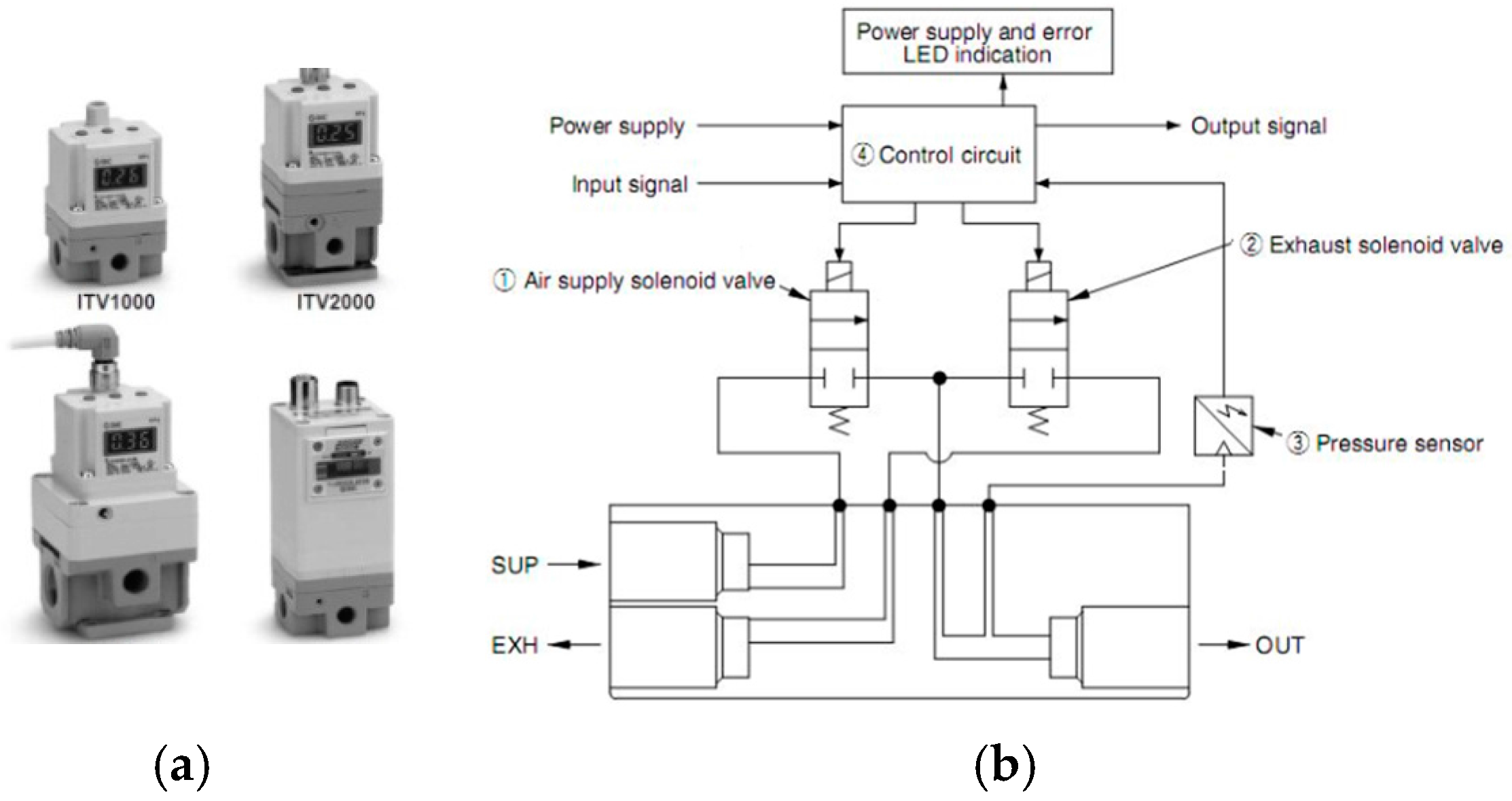
Photo Credit by: bing.com / solenoid smc wiring
How To Wire A Solenoid Valve?
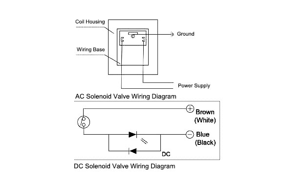
Photo Credit by: bing.com / solenoid valve wiring wire dc ac diagram although poeple simple but
28 Solenoid Valve Wiring Diagram - Wiring Database 2020

Photo Credit by: bing.com / valve wiring diagram port solenoid way motorised sunvic info
Asco Solenoid Valve 8262 Wiring Diagram

Photo Credit by: bing.com / solenoid asco valve diagram wiring hat red valves way series solely designed fluid
Solenoid Valve Wiring Diagram - Free Wiring Diagram

Photo Credit by: bing.com / wiring solenoid valve diagram schematic
View Wiring Diagram Solenoid Valve Pictures - Decorados De Uñas

Photo Credit by: bing.com /


