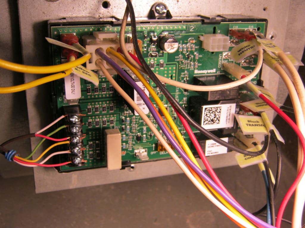
Diagram wiring honeywell board furnace control
Table of Contents
Table of Contents
A wiring diagram is essential for ensuring your HVAC system runs smoothly. The St9120u Wiring Diagram is a crucial tool for those dealing with electronic control boards and HVAC systems. Proper installation and maintenance of electronic control boards are necessary to ensure the longevity of your HVAC system. This post provides an in-depth understanding of St9120u Wiring Diagram and its significance in HVAC systems. Read on to learn everything you need to know about St9120u Wiring Diagram.
The Pain Points of St9120u Wiring Diagram
Electronic control boards are bound to wear out after continued usage, leading to system failures. Troubleshooting and identifying the fault can be difficult without the necessary diagram. It can also be challenging to install a new board without a clear understanding of the connections. Additionally, without proper wiring, the system may underperform or face constant breakdowns, leading to costly repairs.
The Target of St9120u Wiring Diagram
St9120u Wiring Diagram is designed for technicians responsible for troubleshooting, repairing, or installing HVAC electronic control boards. The diagram comes with symbols, colors, and lines indicating how the system operates and the component connections. The board’s layout, terminal numbering, wire coloring, and control board adjustment configurator are also included in the diagram.
Summary of St9120u Wiring Diagram’s Significance
St9120u Wiring Diagram is critical for HVAC technicians, ensuring efficient troubleshooting, maintenance, and installation of electronic control boards. Professionals must follow the wiring diagram’s guidelines to avoid system failures, underperformance, breakdowns, and costly repairs.
Personal Experience with St9120u Wiring Diagram
As an HVAC technician for several years, I have firsthand experience with the St9120u Wiring Diagram. The diagram has been fundamental in my work and has saved me time and resources in many instances. Whenever I am troubleshooting or installing an electronic control board, I refer to the St9120u Wiring Diagram’s connections, colors, and diagrams to ensure that the system runs efficiently, minimizing repairs and system failures. The diagram has made my work more manageable and reduced downtime for my clients.
 How to Use St9120u Wiring Diagram
The first step when using St9120u Wiring Diagram is to identify the specific board model and the manufacturer’s installation instructions. Next, locate the diagram, which is usually included in the manual or comes with the board package. Carefully read through the symbol guide, which outlines the different components, colors, and lines on the diagram. Finally, follow the wiring diagram’s connections, ensuring that you match the wire colors, plug terminal numbers, and control board adjustment configurator with the respective components.
 ### Understanding St9120u Wiring Diagram Symbols
The symbols on the St9120u Wiring Diagram represent various components used in the system, such as resistors, capacitors, transformers, and relays. The symbols are color-coded, with each color representing a specific wire or connection. The lines on the diagram show the circuits and connections between components, indicating the flow of current and voltage throughout the system.
 #### The Importance of Following St9120u Wiring Diagram
Following St9120u Wiring Diagram when troubleshooting, repairing, or installing electronic control boards is essential for the proper functioning of your HVAC system. The diagram provides instructions for proper connections and ensures that the system runs efficiently, reducing repair and maintenance costs.
 Frequently Asked Questions (FAQ) about St9120u Wiring Diagram
Q: Can I use a generic wiring diagram for my electronic control board?
A: No, electronic control boards differ in design and configuration, requiring specific wiring diagrams from the manufacturer. Using a generic diagram may lead to system failures or underperformance.
Q: Can I install an electronic control board without referring to the wiring diagram?
A: No, electronic control board installation must be strictly according to the manufacturer’s instructions and the St9120u Wiring Diagram. Failure to follow the instructions may lead to system failures or underperformance.
Q: How can I identify the right wiring diagram for my electronic control board?
A: The wiring diagram is usually included in the board’s manual or the board package. You can also contact the manufacturer or supplier for the correct wiring diagram.
Q: Can I reuse an electronic control board after replacing it with a new one?
A: Yes, you can reuse the old board as long as it is in good condition and compatible with the system.
Conclusion of St9120u Wiring Diagram
St9120u Wiring Diagram is an essential tool for HVAC technicians when troubleshooting, repairing, or installing electronic control boards. Following the diagram’s instructions ensures that the system runs efficiently, minimizes downtime, reduces repair costs, and prolongs the HVAC system’s lifespan. HVAC technicians must understand and use St9120u Wiring Diagram to ensure that the HVAC system operates to its full potential.
Gallery
St9120U Wiring Diagram – Easy Wiring

Photo Credit by: bing.com /
St9120u Wiring Diagram - Complete Wiring Schemas

Photo Credit by: bing.com / wiring diagram motor blower
St9120u Wiring Diagram - Complete Wiring Schemas

Photo Credit by: bing.com / wiring diagram furnace
St9120u Wiring Diagram - Complete Wiring Schemas

Photo Credit by: bing.com / wiring diagram
St9120u Wiring Diagram - Complete Wiring Schemas

Photo Credit by: bing.com / wiring
St9120U Wiring Diagram – Easy Wiring

Photo Credit by: bing.com /
How Do I Convert A St9120C2002 Electronic Control Board To A

Photo Credit by: bing.com / wiring convert electronic control board diagram hvac
St9120u Wiring Diagram - Complete Wiring Schemas

Photo Credit by: bing.com / wiring diagram honeywell
St9120u Wiring Diagram - Complete Wiring Schemas
Photo Credit by: bing.com / diagram wiring honeywell board furnace control
St9120u Wiring Diagram - Complete Wiring Schemas

Photo Credit by: bing.com / vent smart wiring diagram system arduino messages


