Tb6560 wiring diagram
Table of Contents
Table of Contents
Are you struggling to understand the Tb6560 Wiring Diagram? Look no further! In this article, we will break down what the Tb6560 Wiring Diagram is, its target and how it can help you with your projects.
Pain Points
For many DIY enthusiasts, wiring diagrams can be overwhelming and challenging to understand. Circuit diagrams can be complicated, especially if it’s your first time working on a project that requires one. This complexity can lead to errors when designing circuits, which can not only be frustrating but also costly.
Target of Tb6560 Wiring Diagram
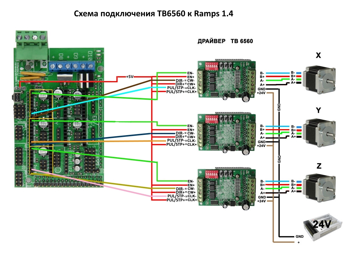
The Tb6560 Wiring Diagram is a schematic representation of how to connect the driver circuit to the stepper motor. It helps you understand how to use a Tb6560 driver board to control stepper motors to achieve precision control. This wiring guide serves as a map for carrying out your project properly.
Summary of Main Points
The Tb6560 Wiring Diagram is a representation of how to connect the driver circuit to the stepper motor. It’s essential to understand this diagram to achieve precision control. Without understanding this, circuit diagrams can be difficult and may lead to costly errors during the project implementation.
Tb6560 Wiring Diagram Explained
The TB6560 is a PWM chopper type single chip bipolar sinusoidal micro-step stepping motor driver. It is widely used in CNC machines and other projects. However, this driver needs a reliable wiring connection to support stepper motor movement. The wiring diagram shows how the driver connects the stepper motor with control signals, ground, and power supply. Understanding the wiring diagram is an essential step in ensuring that your project runs smoothly.
 Benefits of Using the Tb6560 Wiring Diagram
The Tb6560 Wiring Diagram is handy for hobbyists and experts alike for their CNC and other projects. Following this diagram will help you to acquire the right electronics skill to understand stepper motor control. The system supports pulse/direction or CW/CCW control modes, making it compatible with most microcontrollers like Arduino, Raspberry Pi, PLC, and PC-based motion controllers.
This guide provides a clear and comprehensive illustration of how to interface with the Tb6560 micro-stepping driver from various controllers.
 ### The Anatomy of the Tb6560 Wiring Diagram
Understanding the different components of the wiring diagram is crucial for any project that uses the Tb6560 driver board. The diagram illustrates the inputs, outputs, and power supply through the following symbols:
- Black dots: connection points
- Lines: wires or electrical conductors
- Triangle pointing downwards: ground
- Square: power supply
 #### Troubleshooting the Tb6560 Wiring Diagram
When you encounter problems with your Tb6560 wiring diagram, it may be challenging to figure out where the issue lies. One of the most common issues is incorrect wiring. Check that all the wires are connected correctly and that there are no loose connections. If you’re still experiencing issues, try checking the voltage levels and make adjustments as needed.
 Question and Answer
Here are a few commonly asked questions related to the Tb6560 Wiring Diagram:
What is a Tb6560 driver board?
A Tb6560 driver board is an electronic device that controls stepper motors used in various projects.
What is a wiring diagram?
A wiring diagram is a schematic illustration of how circuit parts are connected.
What is the importance of a wiring diagram?
A wiring diagram helps to understand the layout and interaction of various components in a circuit, reducing the likelihood of errors and streamlining the project.
Do all stepper motors need a driver board?
No, not all stepper motors need a driver board. The driver is necessary when the motor device’s load capacity or inductance exceeds what the control circuit can do efficiently.
Conclusion of Tb6560 Wiring Diagram
The Tb6560 Wiring Diagram is an essential tool for controlling stepper motors used in various projects. Understanding the wiring diagram will help you achieve precision control and minimize errors in your DIY projects. By following the wiring diagram, you can avoid costly mistakes and take your DIY project to the next level!
Gallery
Tb6560 Wiring Diagram | Wiring Diagram

Photo Credit by: bing.com / wiring tb6560 stepper tb6600 arduino drivers reprap nema23 nema17 swapping 3f91 46e5 bc5c annawiringdiagram
Introduction To Tb6560 - Projectiot123 Technology Information Website
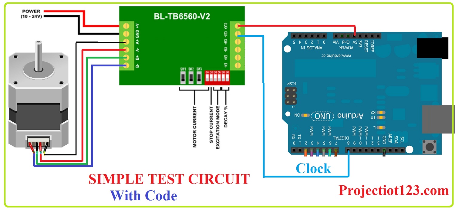
Photo Credit by: bing.com / tb6560 stepper projectiot123 pinout
Tb6560 Wiring Diagram - Cadician’s Blog
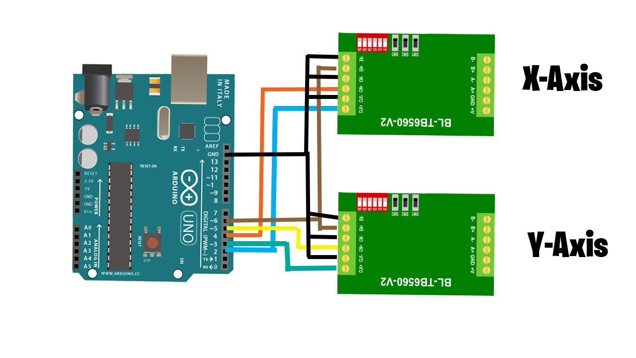
Photo Credit by: bing.com / tb6560 stepper
TB6560-Stepper-Motor-Driver-with-Arduino-UNO-Wiring-Diagram-Schematic

Photo Credit by: bing.com / tb6560 arduino
Tb6560 Wiring Diagram - Cadician’s Blog
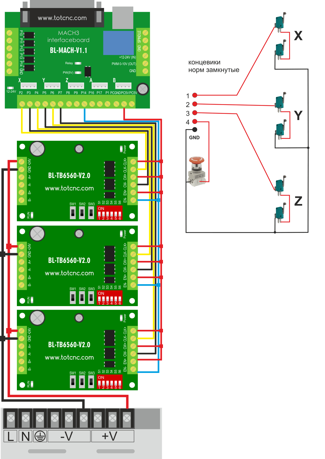
Photo Credit by: bing.com / tb6560 wiring stepper
Introduction To Tb6560 - Projectiot123 Technology Information Website
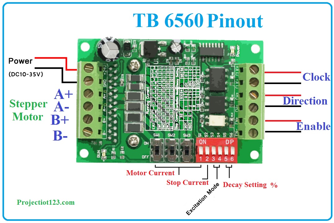
Photo Credit by: bing.com / tb6560 pinout projectiot123
2835 Tb6560 Wiring Diagram ZIP Download ~ 509 DOC Download

Photo Credit by: bing.com /
Tb6560 Wiring Diagram - Complete Wiring Schemas
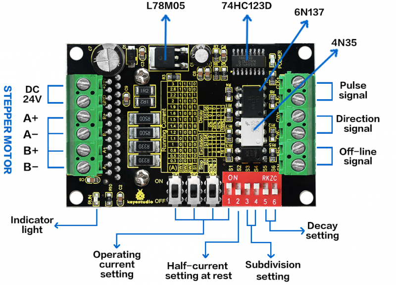
Photo Credit by: bing.com / tb6560 stepper
Tb6560 Wiring Diagram
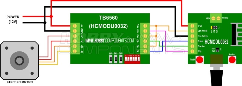
Photo Credit by: bing.com / tb6560 stepper hobbycomponents wire pwm pul direction mainly stepstick
Tb6560 Wiring Diagram

Photo Credit by: bing.com / tb6560 coil correctly stepper insulate termination each


