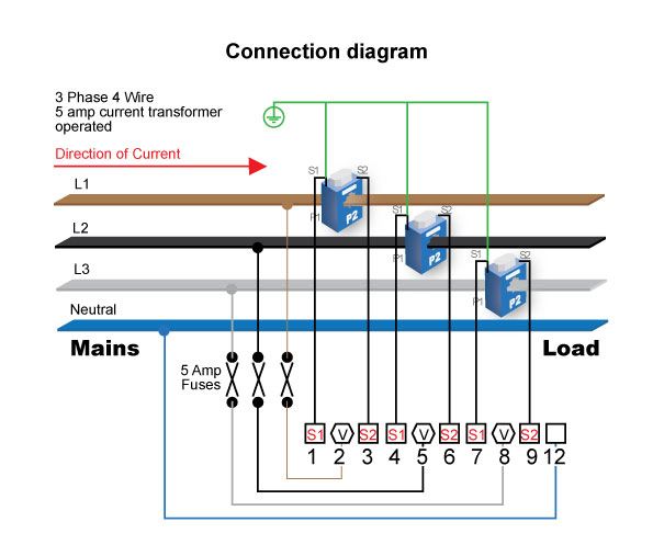
Ac 3 phase 4 wire static kwh meter ct wiring diagram
Table of Contents
Table of Contents
Are you looking for information about Three Phase Ct Meter Wiring Diagram? Understanding wiring diagram is an essential component when attempting to understand and troubleshoot electrical circuits. Three Phase Ct Meter Wiring Diagram involves the connection of current transformers to obtain the required metering.
When it comes to Three Phase Ct Meter Wiring Diagram, there are many pain points that you might encounter. One of the main problems that people tend to face is the complexity of the wiring diagram. You need to understand the various components and how they are connected to each other to ensure the efficient functioning of the system. Some people often find it challenging to understand the different types of wires and how they connect to the meters, thus experiencing a delay in the installation process.
The target of Three Phase Ct Meter Wiring Diagram is to help you understand the connection of the current transformers and obtain the required metering needs of the system. The wiring diagram is an essential aspect of this process, and it’s necessary to ensure that it’s done correctly to avoid any electrical problems later on.
To summarize, Three Phase Ct Meter Wiring Diagram involves the connection of current transformers to obtain the required metering. It’s essential to understand the various components and how they interconnect to one another. Failure to do so could lead to electrical problems down the line.
What is Three Phase Ct Meter Wiring Diagram and its target?
Three-phase CT meters are used to measure the amount of electrical energy consumed by different types of equipment. These meters are widely used in industries, commercial buildings, and residential homes to monitor energy consumption. The target of Three Phase Ct Meter Wiring Diagram is to help you understand the wiring diagram used for connecting the current transformers in the meter system to obtain the required metering.
As an electrician, I’ve had experience working with Three Phase Ct Meter Wiring Diagram. One such instance was when I was working on installing a CT meter for a client. The wiring diagram for Three Phase Ct Meter was quite complex, and I had to spend a lot of time making sure that everything was connected correctly. However, it’s essential to understand that these systems are essential in monitoring energy consumption, and with proper installation, they can provide accurate readings without any glitches.
How to Connect Three Phase Ct Meter Wiring Diagram?
The Three Phase Ct Meter Wiring Diagram involves connecting the current transformers to the meters. The connection process involves installing the CTs and the meters alongside the circuits to be metered. Here are some steps to follow when connecting Three Phase Ct Meter Wiring Diagram:
Step 1:
Start by mounting the CTs close to the meter box. Ensure that the CTs are installed correctly and are tight to avoid any inaccuracy in the readings.
Step 2:
Locate the main circuit breaker and turn it off before you start wiring.
Step 3:
After you turn off the main circuit breaker, connect the CTs to the phase conductors. Connect the primary conductor from the breaker to the CT primary. Then connect the secondary conductors from the CT to the connection terminals of the meter.
Step 4:
Install the meter into the mounting box and connect the live conductors to the terminal blocks of the meter as per the Three Phase Ct Meter Wiring Diagram.
Step 5:
Test the meter installation by powering up the breaker and ensure that the readings are being shown correctly.
Why is Three Phase Ct Meter Wiring Diagram necessary?
Three Phase Ct Meter Wiring Diagram is a necessary component of installing CT meters. Without proper wiring, the system may not work, leading to errors in the meter readings. Furthermore, improper wiring could lead to electrical faults, and in worst cases, lead to electrical accidents. Proper wiring also ensures the accuracy of the readings, which is essential when monitoring energy consumption.
Question and Answer about Three Phase Ct Meter Wiring Diagram:
Q: What could go wrong if I don’t follow the Three Phase Ct Meter Wiring Diagram properly?
A: Improper wiring could lead to electrical faults, and in worst cases, electrical accidents could occur. Furthermore, the readings may not be accurate, which could lead to incorrect billing statements.
Q: Can I install a CT meter on my own, or do I need an electrician?
A: It’s best to seek the services of a licensed electrician to install a CT meter. This is because the wiring diagram could be complex, and proper wiring is essential to ensure that the system works correctly.
Q: Is accuracy essential when monitoring energy consumption?
A: Yes, accuracy is essential. Accurate meter readings are vital for proper monitoring of energy consumption, and without proper readings, billing statements can be incorrect. Additionally, it’s essential to have accurate readings to identify areas of energy waste and take corrective measures.
Q: How can I ensure that the Three Phase Ct Meter Wiring Diagram is correct?
A: It’s best to consult an electrician to ensure that the wiring diagram is done correctly. An electrician has the expertise required to install the CT meter and ensure that the wiring is done correctly.
Conclusion of Three Phase Ct Meter Wiring Diagram
In conclusion, Three Phase Ct Meter Wiring Diagram is essential for connecting the current transformers in the meter system to obtain the required metering. Therefore, it’s necessary to seek the services of a qualified electrician to ensure that the wiring is done correctly. Accurate meter readings are essential for monitoring energy consumption, identifying areas of energy waste, and taking corrective measures.
Gallery
Ct Meter Wiring Diagram - Wiring Diagram

Photo Credit by: bing.com / ct
Electrical Standards: Energy Meter Connection;Single Phase; Three Phase

Photo Credit by: bing.com / energy connection operated
Ac 3 Phase 4 Wire Static Kwh Meter & CT Wiring Diagram - YouTube

Photo Credit by: bing.com / kwh
3 Phase Current Transformer Wiring Diagram - Free Wiring Diagram

Photo Credit by: bing.com / transformer wiring current diagram phase electrical ct meter coil three installation wire ammeter power ampere supply connection diagrams digital transformers
How To Read 3 Phase Meter Reading - Joseph Franco’s Reading Worksheets

Photo Credit by: bing.com / kwh electricity quora
7 How To Wire A Ct Meter Lates - Wiring Diagram Bantuanbpjs.com

Photo Credit by: bing.com /
Digital Ammeter Wiring With Current Transformer - CT Coil
Photo Credit by: bing.com / meter ammeter transformer connections installation solar
DTS 541 CT | Autometers

Photo Credit by: bing.com / wiring dts
3 Phase KWh Meter Wiring Complete Guide
Photo Credit by: bing.com / kwh meter phase wiring diagram three wire complete
Ct Kwh Meter Wiring Diagram / Power Monitoring Single 3 Phase And

Photo Credit by: bing.com / ct phase kwh metering brothers generator operated


