Accelerator pedal position sensor wiring diagram
Table of Contents
Table of Contents
When it comes to maintaining and repairing your vehicle, there are many components and systems that you have to stay on top of. One important component that often goes overlooked is the Throttle Position Sensor Wiring Diagram. The Throttle Position Sensor Wiring Diagram plays a crucial role in your vehicle’s performance and overall functionality, making it imperative that you understand how it works and how to properly maintain it.
Pain Points Related to Throttle Position Sensor Wiring Diagram
Even if you’re an experienced mechanic, the Throttle Position Sensor Wiring Diagram can be a bit tricky to deal with. Not only is it difficult to access in some vehicles, but the wiring diagram itself can be confusing if you’re not familiar with it. Additionally, a malfunctioning throttle position sensor can cause a variety of problems, including increased fuel consumption and reduced engine performance, making it essential to keep it in good condition.
What is Throttle Position Sensor Wiring Diagram?
The Throttle Position Sensor (TPS) Wiring Diagram is a part of your vehicle’s electronic engine management system. The sensor detects the position of your throttle and sends that information to your car’s computer, which then uses that information to regulate your engine’s performance. The wiring diagram tells you how to connect the TPS to your vehicle’s computer, allowing them to communicate effectively.
Main Points about Throttle Position Sensor Wiring Diagram
The Throttle Position Sensor Wiring Diagram is a critical component that helps ensure your vehicle runs smoothly. It can be confusing to deal with at times, but it’s essential to keep it maintained properly so that it doesn’t cause problems later on. Remember: your vehicle’s performance is only as good as the components that make it up, so it’s crucial to stay on top of maintenance and repairs.
Throttle Position Sensor Wiring Diagram: A Personal Experience
I had a personal experience with a faulty Throttle Position Sensor Wiring Diagram a few years ago. My car was running rough, and I couldn’t figure out why. After doing some research, I discovered that the TPS was malfunctioning, causing my car’s computer to receive incorrect information about the throttle position. After replacing the TPS and re-wiring it according to the Wiring Diagram, my car ran like new again.
If you’re experiencing similar problems with your vehicle, it’s essential to check the TPS and its wiring to ensure that they’re working correctly.
How to Maintain Your Throttle Position Sensor Wiring Diagram?
When it comes to maintaining your Throttle Position Sensor Wiring Diagram, there are a few things you can do to keep it in tip-top shape. Firstly, you should regularly clean and inspect the wiring to ensure it’s free of dirt and debris. Additionally, you should check the TPS itself to make sure it’s functioning correctly, and replace it if it’s not.
Why is the Throttle Position Sensor Wiring Diagram Essential?
The Throttle Position Sensor Wiring Diagram is essential because it ensures that your vehicle’s engine is functioning correctly. Without it, your car wouldn’t be able to regulate the throttle properly, leading to reduced engine performance and other issues. Moreover, the TPS Wiring Diagram is a vital part of your vehicle’s electronic engine management system, so it must be maintained and repaired when necessary.
How to Troubleshoot with Throttle Position Sensor Wiring Diagram?
If you’re experiencing issues with your Throttle Position Sensor Wiring Diagram, there are a few things you can do to troubleshoot the problem. Firstly, you should check the wiring to make sure it’s connected correctly and free of dirt and debris. Additionally, you can test the TPS itself to see if it’s functioning correctly using a multimeter or similar tool.
Question and Answer
Q: What happens if the Throttle Position Sensor Wiring Diagram is faulty?
A: If the Throttle Position Sensor Wiring Diagram is faulty, your vehicle’s engine may experience a variety of issues. Some common symptoms of a malfunctioning TPS include rough idling, poor acceleration, and increased fuel consumption.
Q: How often should I check my Throttle Position Sensor Wiring Diagram?
A: You should check your Throttle Position Sensor Wiring Diagram regularly, preferably as part of your vehicle’s routine maintenance schedule. However, if you suspect there is an issue with your TPS, it’s essential to address it as soon as possible to avoid further problems.
Q: Can I replace the Throttle Position Sensor myself?
A: While it’s possible to replace the Throttle Position Sensor yourself, we recommend leaving it to a professional mechanic if you’re not experienced with car repairs. Replacing the TPS requires special tools and knowledge and can be dangerous if not done correctly.
Q: Can a faulty Throttle Position Sensor damage my engine?
A: Yes, a faulty Throttle Position Sensor Wiring Diagram can cause a variety of issues that may eventually lead to engine damage if not addressed. If you suspect there is an issue with your TPS, it’s crucial to have it checked and repaired as soon as possible to avoid further problems.
Conclusion of Throttle Position Sensor Wiring Diagram
The Throttle Position Sensor Wiring Diagram is a crucial component in your vehicle’s engine management system, and it’s essential to maintain and repair it as needed. By regularly checking the TPS and its wiring and addressing any issues promptly, you can avoid many problems down the road and ensure your vehicle runs smoothly for years to come.
Gallery
2008 F250 5.4 Throttle Position Sensor Wiring Diagram

Photo Credit by: bing.com / powerstroke wiring f250 throttle 2002
1999 Civic Wiring Sensor

Photo Credit by: bing.com / throttle tps wire eec efi schematron
Throttle Position Sensor Wiring Diagram - Cadician’s Blog
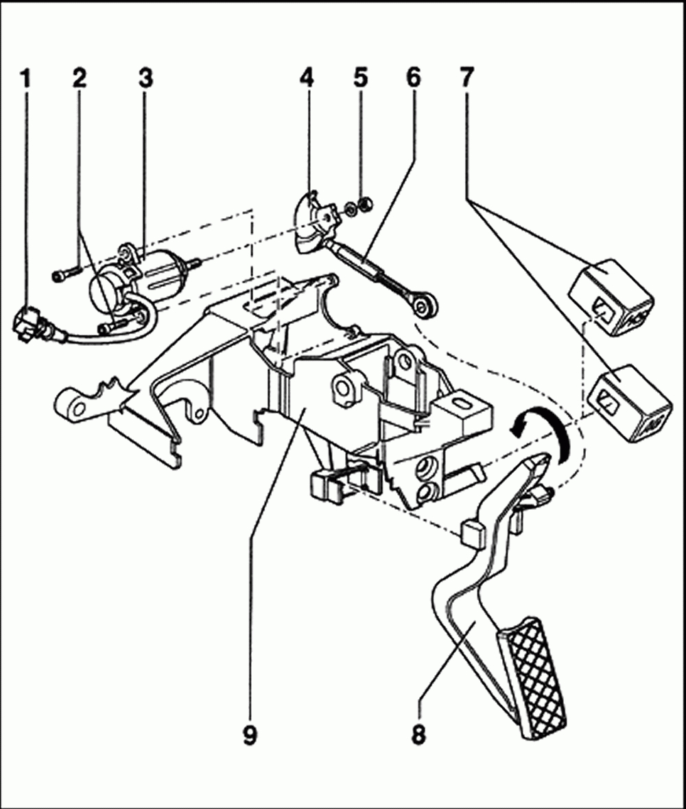
Photo Credit by: bing.com / wiring tps pedal accelerator controls dtc p1705 2020cadillac
| Repair Guides | Electronic Engine Controls | Throttle Position Sensor

Photo Credit by: bing.com / sensor throttle position tps engine wiring diagram 8l autozone fig tell working controls electronic repair
| Repair Guides | Fuel Injected Electronic Engine Controls | Throttle

Photo Credit by: bing.com / wiring diagram sensor chevy tps throttle position ecm location tbi s10 wire 1990 astro 1992 body color need repair autozone
Throttle Position Sensor Wiring Diagram - Complete Wiring Schemas

Photo Credit by: bing.com / throttle tps accelerator
Throttle Position Sensor Wiring Diagram 2004 Ford Mustang 3.9

Photo Credit by: bing.com / wiring diagram sensor maf throttle ford bosch 2004 position mustang diagrams wires
Throttle Position Sensor Problem? - RX8Club.com
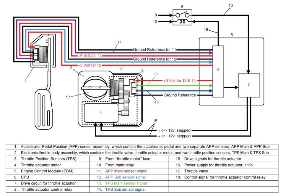
Photo Credit by: bing.com / wiring diagram throttle sensor position toyota problem control electronic sienna 2002 dbw bank pedal accelerator circuit denso 2005 rx8club dtc
Accelerator Pedal Position Sensor Wiring Diagram - Cadician’s Blog
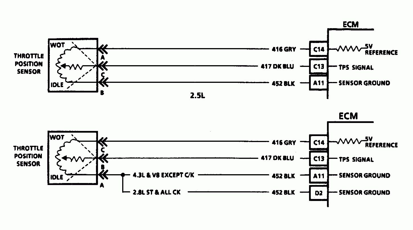
Photo Credit by: bing.com / wiring sensor throttle diagram position accelerator gm pedal chevy s10 tps blazer body sensors library fuel maf map 1993 1994
HOW DO I TELL IF MY THROTTLE POSITION SENSOR IS WORKING OR NOT

Photo Credit by: bing.com / sensor position throttle tps wiring diagram repair tell working engine autozone if guide 3l fig


