How does ne555 timer circuit work
Table of Contents
Table of Contents
Do you find yourself in need of a Timer Off Wiring Diagram but aren’t sure where to turn? Look no further! In this article, we will discuss the ins and outs of Timer Off Wiring Diagram and provide you with all the information you need to know to get started.
The Pain Points of Timer Off Wiring Diagram
Timer Off Wiring Diagram can be a daunting task, especially for those who are not well-versed in electrical wiring. Trying to figure out the correct wiring configuration can be time-consuming and frustrating, leading many to simply give up and call a professional to handle the job. But understanding the process and having a clear diagram can save time and money in the long run.
The Target of Timer Off Wiring Diagram
Timer Off Wiring Diagram is aimed at those who need to install a timing circuit that will turn off a device after a specific amount of time. This is a common need in many electrical applications, and having a proper understanding of Timer Off Wiring Diagram is essential for both safety and functionality.
Main Points About Timer Off Wiring Diagram
Timer Off Wiring Diagram is an important concept to understand for both professionals and those who are simply looking to complete a DIY project. By having a clear understanding of the wiring configuration, you can ensure the proper functioning of your electronic devices and avoid dangerous situations. This article will provide an in-depth explanation of the topic, including how it works, common applications, and step-by-step instructions for installation.
Explaining Timer Off Wiring Diagram in Depth
Timer Off Wiring Diagram is a circuit that will deactivate a device after a specific amount of time has passed. One of the most common uses for this circuit is to switch off a lighting system after a certain period of time to conserve energy. The circuit works by using an electric timer that interrupts the power supply to the device being controlled after the preset time has elapsed.
When it comes to Timer Off Wiring Diagram, there are a few key components that must be identified. These include the electric timer, the relay, and the power supply. The electric timer controls the length of time that the device remains active, while the relay acts as a remote switch that cuts off the power supply once the preset time has elapsed.
One of the most important things to keep in mind when working with Timer Off Wiring Diagram is safety. It is essential to ensure that all wiring is done properly and that the circuit is correctly grounded to avoid electrical shock or other hazards. Working with a professional electrician is always recommended to avoid any potential issues.
Common Applications of Timer Off Wiring Diagram
Timer Off Wiring Diagram can be used in a variety of applications. Some of the most common include security lighting, irrigation systems, and HVAC systems. This circuit is also often used in commercial applications, such as in process control systems and building automation systems. By using Timer Off Wiring Diagram, the device can be switched off automatically after a specific period of time, which can conserve energy and save money in the long run.
Step-by-Step Installation of Timer Off Wiring Diagram
Installing Timer Off Wiring Diagram can be a bit intimidating for those who are not well-versed in electrical wiring. However, by following a few simple steps, it can be done safely and efficiently. First, the power supply to the device being controlled must be turned off to avoid any potential electrical shock. Next, the electric timer, relay, and power supply must be properly connected. Finally, the circuit must be tested to ensure that it is functioning properly.
Personal Experience with Timer Off Wiring Diagram
As an electrician, I have seen many cases where Timer Off Wiring Diagram was essential for both safety and functionality. In one instance, a homeowner had installed a lighting system that remained on 24/7, leading to high energy bills and unnecessary wear and tear on the bulbs. By installing a Timer Off Wiring Diagram, we were able to reduce the energy consumption and extend the life of the bulbs, saving the homeowner money in the long run.
Question and Answer About Timer Off Wiring Diagram
Q: Why is Timer Off Wiring Diagram important?
A: Timer Off Wiring Diagram is important because it allows for the safe and efficient control of electronic devices. By setting a specific time for the device to turn off, energy can be conserved and potential hazards can be avoided.
Q: What types of devices can be controlled with Timer Off Wiring Diagram?
A: Timer Off Wiring Diagram can be used to control a wide variety of devices, including lighting systems, HVAC systems, irrigation systems, and more.
Q: Is it recommended to attempt a Timer Off Wiring Diagram installation on my own?
A: While it is possible to install a Timer Off Wiring Diagram on your own, it is always recommended to work with a professional electrician to ensure that all wiring is done properly and to avoid any potential hazards.
Q: Are there any special considerations to keep in mind when working with Timer Off Wiring Diagram?
A: Safety is paramount when working with Timer Off Wiring Diagram. Always make sure that the power supply is properly turned off and that all wiring is grounded correctly to avoid potential electrical shock or other hazards.
Conclusion of Timer Off Wiring Diagram
Timer Off Wiring Diagram is an essential concept to understand for both professionals and DIY enthusiasts. By having a clear understanding of the wiring configuration, you can ensure the proper functioning of your electronic devices and avoid dangerous situations.
Gallery
Wiring Diagram For Defrost Timer

Photo Credit by: bing.com / timer wiring diagram wire delay relay fan off boiler defrost waterheatertimer diagrams circuit electrical switch data socket schematic schema vent
How To Wire Off Delay Timer | Electrical Wiring Colours, Timer

Photo Credit by: bing.com / timer delay relay wire anly contactor schematron buzzer ah3
Off Delay Timer Wiring Diagram - Wiring Diagram

Photo Credit by: bing.com / delay relay
Delay On Break Timer Wiring Diagram - Hanenhuusholli

Photo Credit by: bing.com / delay relay contactor chanish relays villanveva nereida
On Off Timer Relay Circuit Diagram

Photo Credit by: bing.com / timer delay dayton eeweb circuits ambrasta electrcity
Solid State Timer | Solid State Relay Timer | Electrical Academia

Photo Credit by: bing.com / delay relay schematic relays electricalacademia
Intermatic Pool Pump Timer Wiring Diagram
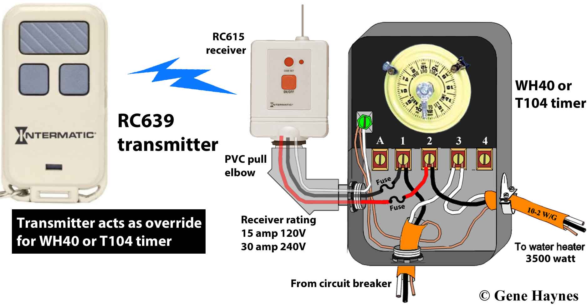
Photo Credit by: bing.com / timer wiring intermatic diagram control remote pool pump wire t104 wh40 heater water eh40 manual override clock diagrams timers hot
Staircase Timer Wiring Diagram - Using On Delay Timer And Relay
Photo Credit by: bing.com / staircase wiring diagram timer relay electrical contactor connection delay using circuit use motor delta control below electricalonline4u very above then
How Does NE555 Timer Circuit Work | Datasheet | Pinout | ElecCircuit.com
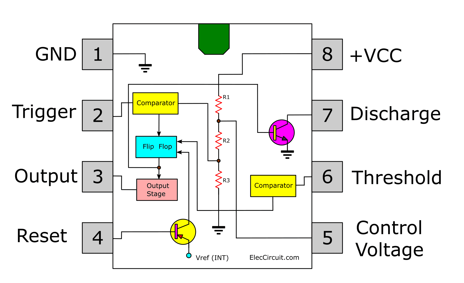
Photo Credit by: bing.com / timer 555 diagram circuit schematic ne555 pinout datasheet works does block circuits flop flip transistor discrete kit eleccircuit connection pins
Timer Off Wiring Diagram - Complete Wiring Schemas
Photo Credit by: bing.com / timer delay volt circuits ignition turned


