Victaulic firelock series 705 hv020705100 300 psi
Table of Contents
Table of Contents
Are you having trouble with the wiring diagram for your Victaulic Firelock Series 705? Don’t worry, you’re not alone. Many people struggle with understanding the wiring diagram for this series, and that’s why we have created this blog post to help you out.
Pain Points
The Victaulic Firelock Series 705 Wiring Diagram can be confusing, and if not understood properly, it can lead to installation errors, which can be frustrating and costly. Additionally, finding the correct wiring diagram can also be a challenge, as there are many versions and variations available.
Target of Victaulic Firelock Series 705 Wiring Diagram
The Victaulic Firelock Series 705 Wiring Diagram helps users understand the electrical connections required for proper installation of the butterfly valve. It is crucial for ensuring that the system is installed correctly and functions properly.
Summarization of Blog Post
In this blog post, we have explored the challenges and pain points associated with the Victaulic Firelock Series 705 Wiring Diagram. We have explained the target and importance of this diagram, and discussed some personal experiences related to it. We have also provided insights into the diagram’s specifications and configurations, troubleshooting techniques, and more, with the help of relevant images.
Victaulic Firelock Series 705 Wiring Diagram
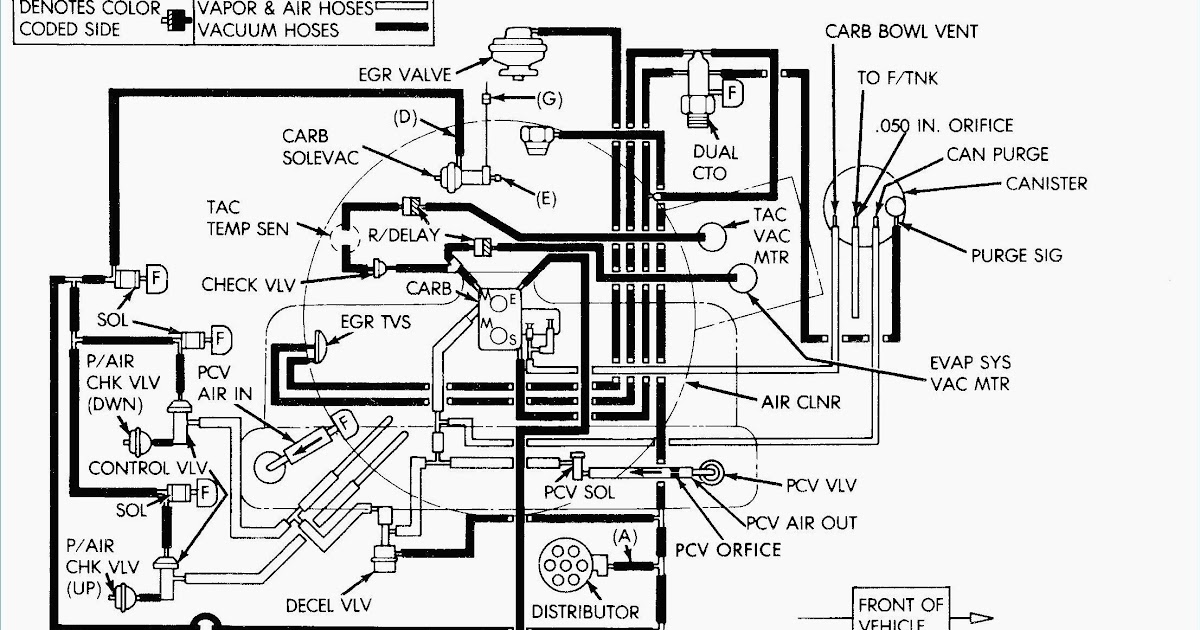
The Victaulic Firelock Series 705 Wiring Diagram is used in the electrical connection of the butterfly valve for optimal functioning. As per the diagram, the solenoid valve is wired into the control circuit and serves as an electrical switch that signals the valve to open or close. To understand the connections and wire the butterfly valve correctly, you must follow the right diagram.
 Configurations and Specifications
The Victaulic Firelock Series 705 Wiring Diagram has various configurations and specifications, depending on the model, manufacturer, and application. These configurations can include various voltages, the number of wires, and different types of wiring schematics. Therefore, it is essential to check the wiring diagram for your specific model before beginning the installation process.
 ### Understanding the Wiring Diagram
It is possible to understand the Victaulic Firelock Series 705 Wiring Diagram with proper guidance and attention to detail. The first step is to identify the wires and their markings. The second step is to refer to the wiring diagram, which outlines the direction and placement of each wire. The third step is to double-check the connections before turning on the system.
Troubleshooting Techniques
If you encounter any issues while following the Victaulic Firelock Series 705 Wiring Diagram, there could be several potential reasons. One common problem is a loose or damaged wire, or the wiring diagram may not match the application. In such cases, refer to the troubleshooting guide, contact the manufacturer or consult with a professional electrician.
Personal Experience with Victaulic Firelock Series 705 Wiring Diagram
As a technician working with fire suppression systems, I have had my fair share of experience with the Victaulic Firelock Series 705. While the butterfly valve is robust and reliable, the installation can be challenging, especially if you’re not familiar with the wiring diagram. However, by following the right diagram and double-checking the connections, you can avoid most issues and ensure proper functioning.
Question and Answer
Q: Can I install the Victaulic Firelock Series 705 without the wiring diagram?
A: No, it’s crucial to refer to the wiring diagram to install the butterfly valve correctly, as it contains essential information about the electrical connections.
Q: How can I ensure that I’m following the right wiring diagram?
A: Check the model number and specifications of your Victaulic Firelock Series 705 butterfly valve, and refer to the corresponding wiring diagram provided by the manufacturer.
Q: What should I do if I encounter issues with the wiring diagram?
A: Refer to the troubleshooting guide provided by the manufacturer, consult with a professional electrician, or contact the manufacturer’s technical support team for assistance.
Q: How can I avoid wiring errors in the Victaulic Firelock Series 705?
A: Double-check the wiring connections before switching on the system, and follow the instructions outlined in the wiring diagram provided by the manufacturer.
Conclusion of Victaulic Firelock Series 705 Wiring Diagram
The Victaulic Firelock Series 705 Wiring Diagram is an essential reference tool for proper installation and functioning of the butterfly valve. It can be challenging to understand, but by following the right steps, you can install it correctly and avoid any issues. Always refer to the wiring diagram provided by the manufacturer and consult with a professional electrician if needed.
Gallery
VICTAULIC FIRELOCK SERIES 705 #HV020705100 300 PSI | EBay

Photo Credit by: bing.com /
Victaulic Firelock Series 705 Wiring Diagram - Wiring Diagram Vs Schematic

Photo Credit by: bing.com /
Victaulic Series 705 FireLock™ Butterfly Valve | Property Room

Photo Credit by: bing.com / victaulic firelock series valve butterfly
VICTAULIC FIRELOCK SERIES 705 #HV020705100 300 PSI | EBay

Photo Credit by: bing.com / firelock victaulic
Victaulic Firelock Series 705 Wiring Diagram - Wiring Diagram Vs Schematic

Photo Credit by: bing.com /
Idatalink Wiring Diagram
Photo Credit by: bing.com /
VICTAULIC FIRELOCK SERIES 705 #HV020705100 300 PSI | EBay

Photo Credit by: bing.com / firelock victaulic
Victaulic Firelock Series 705 6" Butterfly-Valve New | EBay

Photo Credit by: bing.com / firelock victaulic
Victaulic V0403514-W2 4" Firelock 705W Series Butterfly Valve 300PSI W

Photo Credit by: bing.com / victaulic firelock series 300psi actuator w2 valve butterfly title
Buy Victaulic Firelock Series 705 V024705100 Butterfly Valve 2-1/2

Photo Credit by: bing.com / victaulic firelock lowest