Voltmeter with shunt wiring diagram
Table of Contents
Table of Contents
If you’re someone who enjoys do-it-yourself electrical work, then you’ve probably heard of voltmeter with shunt wiring diagram. This is a crucial component when it comes to measuring the current of an electrical system, but many people find it difficult to understand. In this post, we’ll break down the topic in detail and discuss everything you need to know about voltmeter with shunt wiring diagram.
Pain Points Related to Voltmeter With Shunt Wiring Diagram
Many people struggle with understanding how to wire a voltmeter with shunt. This is because it involves connecting multiple wires, and if not done correctly, it can damage the electrical system. Additionally, finding the correct diagrams and instructions online can be overwhelming, as there are so many resources to choose from.
The Target of Voltmeter With Shunt Wiring Diagram
The target of voltmeter with shunt wiring diagram is anyone who wants to measure the current of an electrical system. This includes those who work in the electrical field as well as those who are into DIY electrical projects.
Summary of Main Points
Now that we’ve covered the basics of voltmeter with shunt wiring diagram, let’s summarize some of the main points. It involves connecting multiple wires to measure the current of an electrical system. It’s important to understand the diagrams and instructions before attempting to wire a voltmeter with shunt, as not doing so can cause damage. Finally, this component is essential for anyone who wants to measure the current of an electrical system.
What Is Voltmeter With Shunt Wiring Diagram?
A voltmeter with shunt wiring diagram is a way to connect a voltmeter to an electrical system to measure the current. The shunt is a small resistor that is placed in series with the electrical system, and the voltmeter is connected in parallel to the shunt. This allows the voltmeter to measure the voltage drop across the shunt, which is proportional to the current flowing through the electrical system.
When wiring a voltmeter with shunt, it’s important to follow the correct wiring diagram and instructions. There are many resources online that provide diagrams and instructions, but it’s important to choose a reliable source. Additionally, it’s important to understand the electrical system that you’re working with to ensure that you’re connecting everything correctly.
If you’re new to wiring a voltmeter with shunt, it can be helpful to read tutorials and watch videos online to get a better sense of what’s involved. Many voltmeters come with detailed instructions and diagrams, but it’s still important to do your own research to ensure that you’re doing everything correctly.
Common Mistakes When Wiring a Voltmeter With Shunt
One of the most common mistakes when wiring a voltmeter with shunt is to connect the wires incorrectly. This can cause damage to the voltmeter and the electrical system. Another common mistake is to use the wrong shunt or voltmeter for the electrical system, which can result in inaccurate readings.
To avoid these mistakes, it’s important to carefully read the instructions and wiring diagrams that come with the voltmeter and shunt. It’s also important to understand the electrical system that you’re working with to ensure that you’re choosing the correct components. Finally, it’s important to take your time when wiring a voltmeter with shunt and to double-check your work before turning on the power.
Benefits of Using Voltmeter With Shunt Wiring Diagram
There are many benefits to using a voltmeter with shunt wiring diagram. First, it allows you to measure the current of an electrical system, which is essential for diagnosing problems and planning upgrades. Additionally, it’s a relatively simple component that can be added to most electrical systems, even if they don’t come with a built-in voltmeter.
Finally, using a voltmeter with shunt wiring diagram can save you time and money in the long run. By accurately measuring the current of your electrical system, you can quickly identify problems and fix them before they become serious. Additionally, by planning upgrades based on current measurements, you can save money by only upgrading the components that need it.
Question and Answer
Q. What is a shunt resistor?
A. A shunt resistor is a small resistor that is placed in series with an electrical system to measure the current.
Q. Can I use any voltmeter with a shunt resistor?
A. No, it’s important to choose a voltmeter that is compatible with the shunt resistor and the electrical system you’re working with.
Q. Is it difficult to wire a voltmeter with shunt?
A. Wiring a voltmeter with shunt can be challenging, but with the right instructions and diagrams, it’s relatively simple.
Q. Why is it important to measure the current of an electrical system?
A. Measuring the current of an electrical system is important for diagnosing problems and planning upgrades.
Conclusion of Voltmeter With Shunt Wiring Diagram
In conclusion, voltmeter with shunt wiring diagram is an essential component when it comes to measuring the current of an electrical system. It allows you to diagnose problems and plan upgrades, and it’s a relatively simple component that can be added to most electrical systems. By following the correct instructions and diagrams, you can wire a voltmeter with shunt without damaging your electrical system.
Gallery
Volt Meter Shunt Wiring Diagram Solar - Complete Wiring Schemas

Photo Credit by: bing.com / shunt 100a
Voltmeter With Shunt Wiring Diagram - Complete Wiring Schemas

Photo Credit by: bing.com / voltmeter amps reading wiring
How To Wire Voltmeters For 3 Phase Voltage Measuring - Electricalonline4u

Photo Credit by: bing.com / voltmeter panel measuring circuit voltmeters 4u elektrotechnik
Power Supply - The Issues Of Common Ground With Voltmeter And Ammeters

Photo Credit by: bing.com / voltmeter mete shunt ammeters 12v
3 Wire Voltmeter Wiring Diagram - General Wiring Diagram

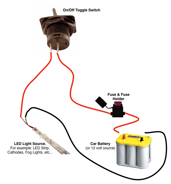
Photo Credit by: bing.com / voltmeter wiring diagram wire gauge volt yellow red car
Voltmeter With Shunt Wiring Diagram - Complete Wiring Schemas

Photo Credit by: bing.com / shunt monitor voltmeter digital drok 50a droking current voltage wiring diagram ammeter
Voltmeter With Shunt Wiring Diagram - Complete Wiring Schemas

Photo Credit by: bing.com / shunt voltmeter current measurement electric resistor ammeter wiring
Build Your Own Battery Box - 4x4Direct 4x4 Hardware Shop

Photo Credit by: bing.com / battery diagram wiring shunt box build amp meter volt own
Voltmeter With Shunt Wiring Diagram - Complete Wiring Schemas

Photo Credit by: bing.com / voltmeter wiring diagram shunt ammeter digital voltage
10 Most Digital Volt, Meter Wiring Diagram Photos - Tone Tastic

Photo Credit by: bing.com / voltmeter ammeter wiring 10a 100v amp dsn voltmetro amperometro amperemeter amperomierz woltomierz cyfrowy dc100v digit ampere china rosso 50a 30v