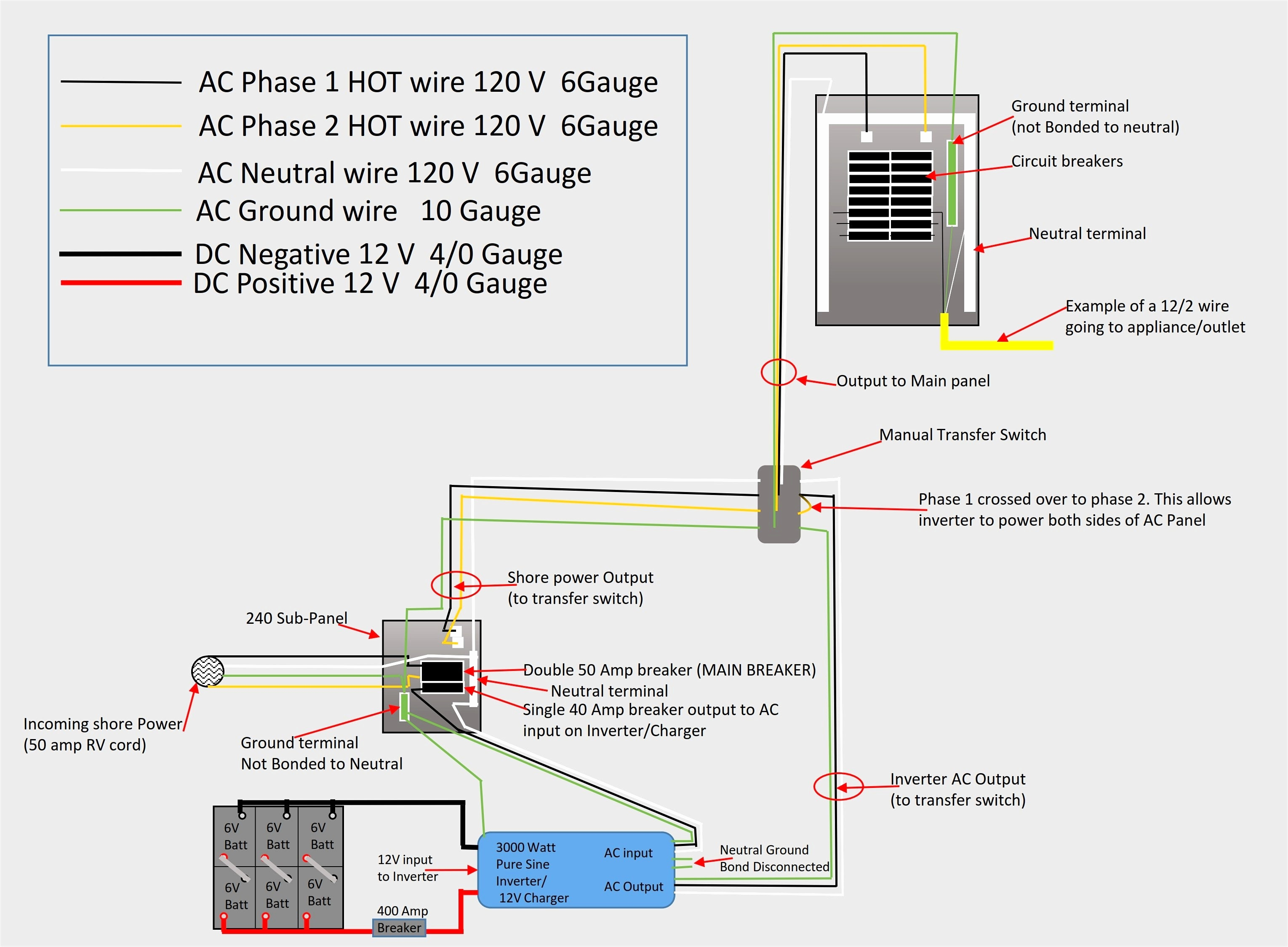
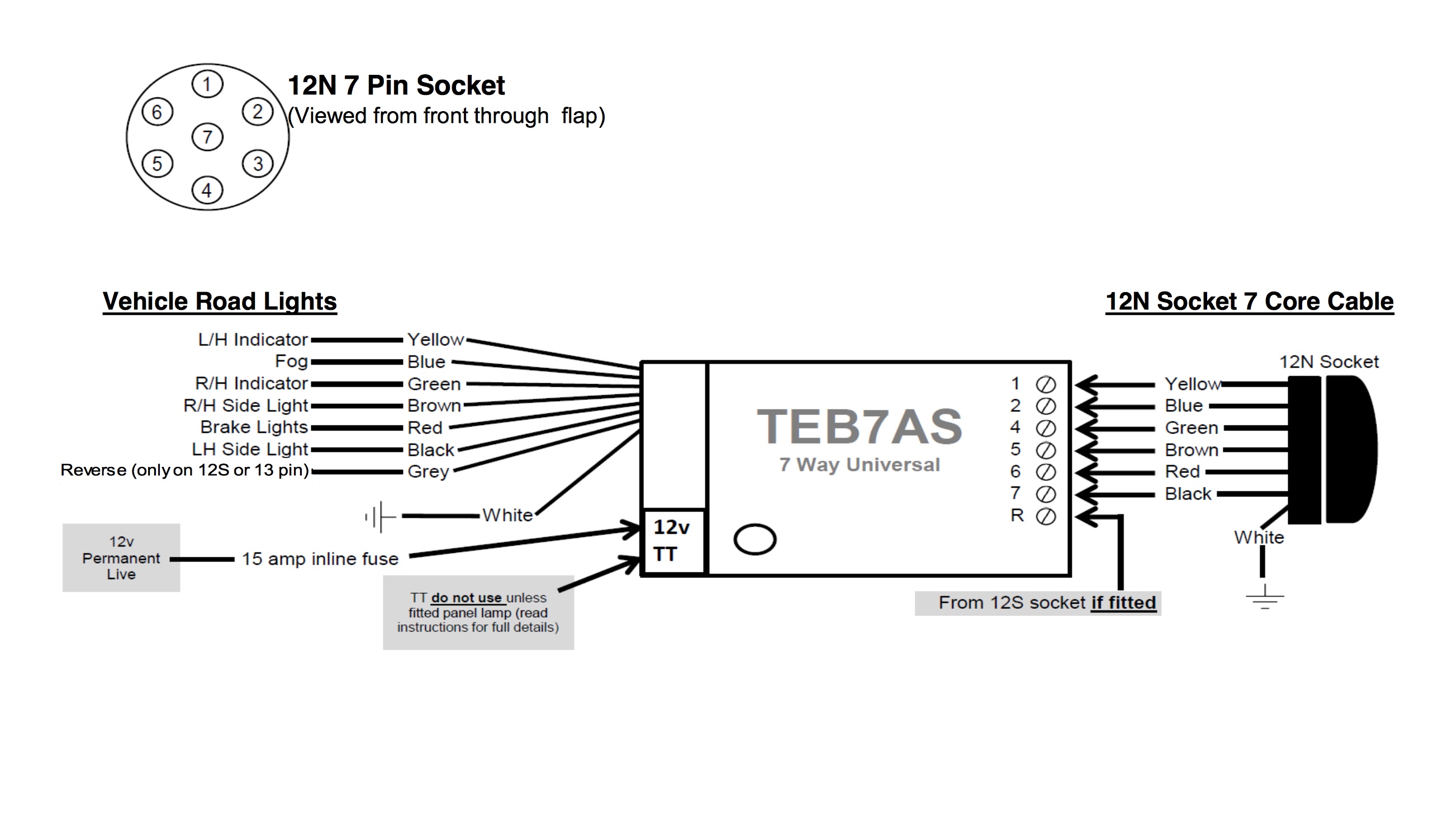
Difference between schematics and circuit diagrams
Table of Contents
Table of Contents
Creating an electronic device or a machine requires assembling different parts that need to be connected correctly to function. One of the essential aspects of this process is creating a wiring diagram or a schematic. While they are similar in nature, they are not identical, and understanding the difference between them is crucial for the success of the project. In this article, we’ll explore Wiring Diagram vs Schematic and explain why it matters.
The Pain Points
Creating an accurate wiring diagram or schematic can be frustrating and time-consuming. It requires a deep understanding of the different components and their interactions. Even a small error can result in costly damages or render the project inoperable. Moreover, interpreting wiring diagrams and schematics can also be challenging, as they use specific symbols and notations that may not be immediately clear to everyone.
The Target of Wiring Diagram vs Schematic
Wiring diagrams and schematics serve the same purpose: to provide a visual representation of the connections between electrical components. However, they differ in their level of detail and complexity. A wiring diagram is a simplified version of a schematic that shows how wires are connected and where they lead. On the other hand, a schematic provides a more detailed view of the circuit, including the individual components, their values, and how they interact with each other.
Summary of Main Points
Understanding the difference between wiring diagrams and schematics is crucial for anyone involved in electronic device or machine assembly. While similar, wiring diagrams are simplified and show only the wire connections, and schematics portray a more detailed view of the circuit. Creating accurate diagrams and schematics can be challenging and time-consuming, but it’s essential to avoid costly damages or a failed project.
My Personal Experience with Wiring Diagram vs Schematic
As an electrical engineer, I’ve worked on numerous projects that required creating wiring diagrams and schematics. In one particular project, we had to assemble a complex machine that required over 50 electrical components to function correctly. Despite our experience, we made a mistake in interpreting the symbols on the schematic, which resulted in a blown fuse and damaged one of the critical pieces. It was a costly lesson, but it taught us the importance of paying close attention to the details and double-checking our work.
The Benefits of Using Wiring Diagrams and Schematics
Using wiring diagrams and schematics can save time, money, and a lot of headaches down the line. They provide a clear and accurate representation of the circuit, making it easier to assemble, diagnose, and repair if necessary. Moreover, they allow multiple people to work on the project simultaneously, as everyone can refer to the same diagrams and schematics. Not using them or using inaccurate ones can result in delays, extra costs, and a failed project.
Going In-Depth about Wiring Diagram vs Schematic
Wiring diagrams and schematics use a set of standardized symbols and notations to represent different electrical components, such as resistors, capacitors, transistors, and switches. It’s essential to have a deep understanding of these symbols to interpret the diagrams and schematics correctly. Wiring diagrams are useful when dealing with simple circuits that have few components, as they show only the connections and wire paths. However, schematics are indispensable when dealing with complex, multi-level circuits that have many components, as they show not only the connections but also the component values and their interactions.
Advantages of Using Wiring Diagrams and Schematics
Using wiring diagrams and schematics offers many benefits, such as:
- Providing a clear and accurate representation of the circuit
- Allowing multiple people to work on the project simultaneously
- Facilitating assembly, diagnosis, and repair of the circuit
- Reducing the risk of errors and damages
- Saving time, money, and effort
Question and Answer
Here are some common questions and answers related to Wiring Diagram vs Schematic:
Q: Can I use a wiring diagram instead of a schematic?
A: It depends on the complexity of the circuit. If it’s simple and has few components, a wiring diagram may be sufficient. However, for more complex circuits, a schematic is necessary to show the individual components and their interactions accurately.
Q: What are some common symbols used in wiring diagrams and schematics?
A: Some common symbols include resistors, capacitors, transistors, switches, diodes, ground, power source, and others. Each symbol has a specific meaning and is used to represent a particular electrical component or property.
Q: How can I create accurate wiring diagrams and schematics?
A: Creating accurate diagrams and schematics requires a deep understanding of the circuit and the individual components. It’s essential to use standardized symbols and notations and double-checking the work for errors or omissions.
Q: Why is it important to use accurate wiring diagrams and schematics?
A: Using accurate diagrams and schematics reduces the risk of errors, damages, and a failed project. It also saves time, money, and effort in the long run and makes assembly, diagnosis, and repair of the circuit easier and more efficient.
Conclusion of Wiring Diagram vs Schematic
Creating accurate wiring diagrams and schematics is crucial for the successful assembly, diagnosis, and repair of electronic devices and machines. They provide a clear and accurate representation of the circuit, making it easier to work on and to avoid errors and damages. While similar, wiring diagrams are simplified and show only the wire connections, and schematics provide a detailed view of the circuit and its components. By understanding the difference between them and using them correctly, you can save time, money, and headaches down the line.
Gallery
Wiring - What’s A Schematic (compared To Other Diagrams)? - Electrical

Photo Credit by: bing.com / diagrams wiring schematic electrical engineering compared other comparable
Schematic Vs. Wiring Diagrams – Basic Motor Control
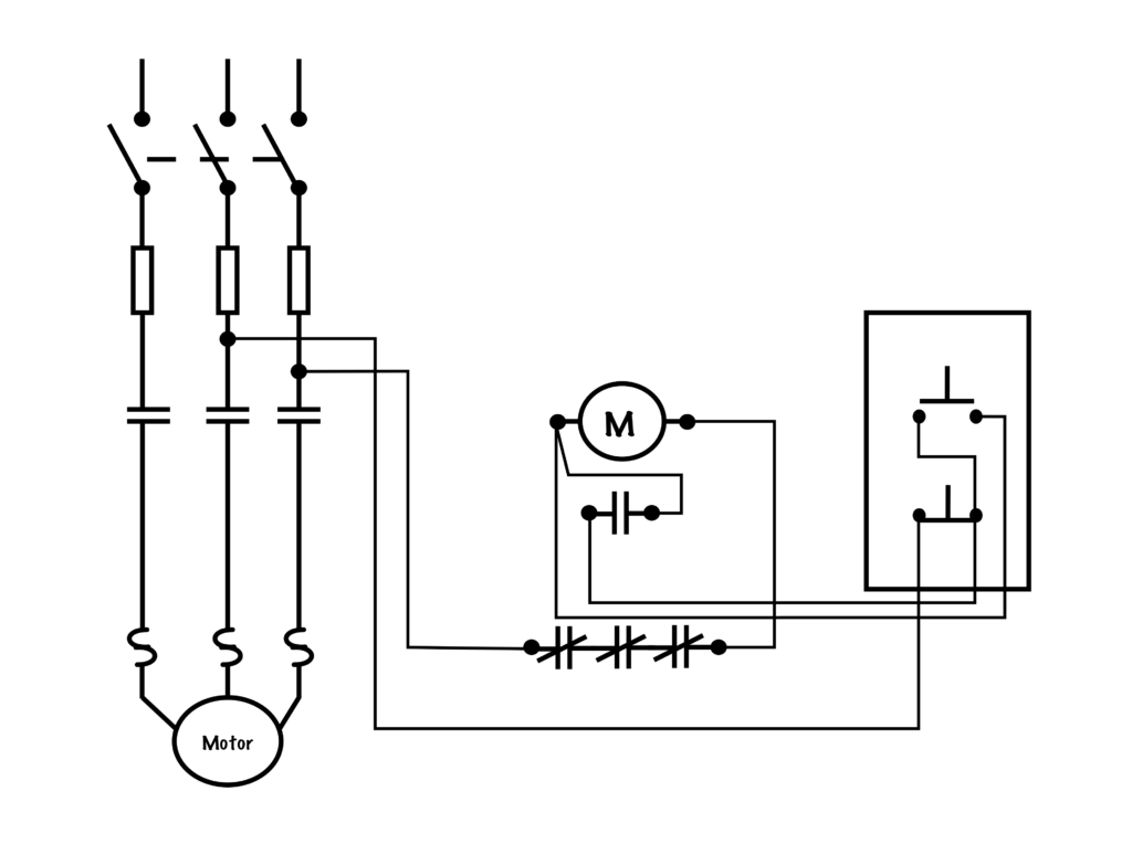
Photo Credit by: bing.com / wiring schematic diagrams vs diagram motor control basic
Difference Between Schematics And Circuit Diagrams
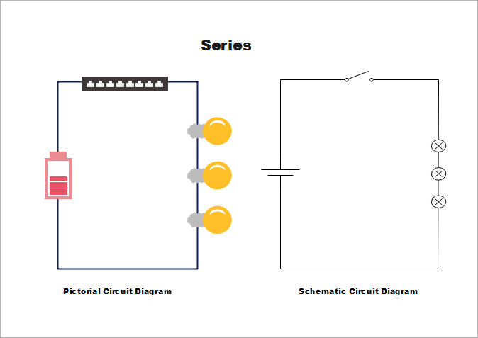
Photo Credit by: bing.com / circuit schematic diagram difference schematics between drawing diagrams pictorial drawings paintingvalley
Vr V7 Engine Wiring Diagram

Photo Credit by: bing.com / commodore fuel ignition vp efi vz nerve schematics jeanjaures37 papan pilih circuit vy alternator glitz unplugged
Schema Electrique 350 Dr - Bois-eco-concept.fr

Photo Credit by: bing.com / wiring ddec intruder 1400 1992 maruti dr650 omni mpfi flh thisoldtractor schematics marauder motorcycle ecm harnes bois battery dr350
Wiring Diagram Vs Schematic - Herbal Saga
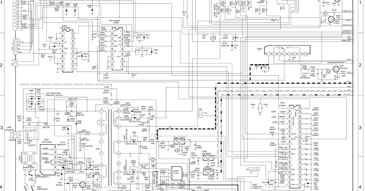
Photo Credit by: bing.com /
VS 1400 Wiring Diagram | This Is A Colored Wiring Diagram Fo… | Flickr
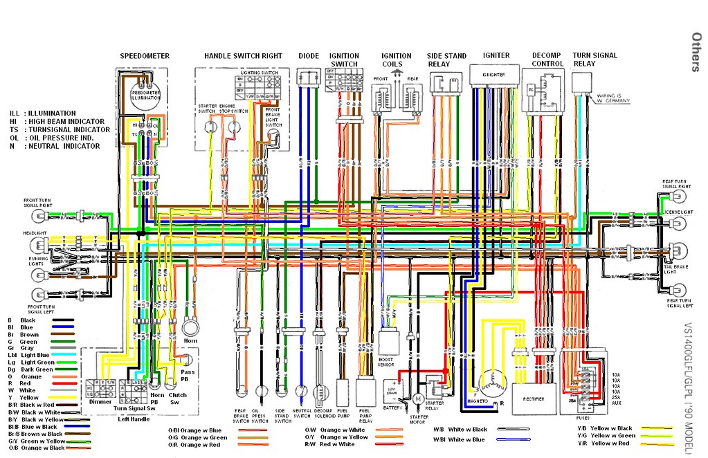
Photo Credit by: bing.com / wiring diagram suzuki 1400 vs marauder 2003 vz800 wr450f vs1400 switch staticflickr flickr bike diagrams colored maytag refrigerator motorcycle t500
⭐Wiring Diagram Vs Schematic⭐ - Stiehl Chainsaw Discounted
Photo Credit by: bing.com /
Owners And Manual: Electrical Wiring Diagram Suzuki VS800 Intruder
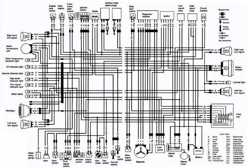
Photo Credit by: bing.com / intruder vs800 ignition iskustva vl1500 uzuki citat concept
Schematic Vs Wiring Diagram

Photo Credit by: bing.com / diagram schematic pcx alternator plumbing

