Gm original equipment pt2712 accelerator pedal position sensor
Table of Contents
Table of Contents
If you’re an automotive enthusiast, you’ll likely understand the importance of having a smoothly functioning accelerator pedal. One component that plays a vital role in this process is the GM Accelerator Pedal Position Sensor Wiring Diagram (APP). The APP sensor helps regulate engine output by constantly monitoring the position of the throttle. In addition to its importance, the wiring diagram of the APP sensor can be quite complex, making it a source of frustration for many people.
Pain Points of Gm Accelerator Pedal Position Sensor Wiring Diagram
When it comes to discussing the pain points of the GM Accelerator Pedal Position Sensor Wiring Diagram, it’s essential to note that the wiring diagram can be confusing to diagnose, causing mechanical issues. This can lead to difficult diagnoses, frustration, and in some cases, the replacement of the entire wiring harness.
Target of Gm Accelerator Pedal Position Sensor Wiring Diagram
The GM Accelerator Pedal Position Sensor Wiring Diagram is the electrical system that connects the accelerator pedal sensor to the engine control module. It is designed to provide an accurate reading of the pedal position and thus control the throttle opening. The system is responsible for sending the correct signal to the engine control module to adjust the throttle position accordingly.
Summary of Key Points
The GM Accelerator Pedal Position Sensor Wiring Diagram can be a source of frustration for many due to its complexity. The wiring diagram is designed to provide an accurate reading of the pedal position and adjust the throttle accordingly.
What is the GM Accelerator Pedal Position Sensor Wiring Diagram’s Target?
The target of the GM Accelerator Pedal Position Sensor Wiring Diagram is to provide a signal to the engine control module that is accurate and reliable. The accelerator pedal varies the voltage and resistance signals in response to the driver’s acceleration demands, then sends this information to the engine control module. The wiring diagram is responsible for ensuring this signal is correct to allow the engine control module to adjust the throttle position accordingly.
From a personal encounter, I once had to deal with a faulty GM Accelerator Pedal Position Sensor Wiring Diagram on my car. I had symptoms of poor acceleration, hesitation, and a check engine light. Upon diagnosing it, the mechanic found that the wiring diagram was at fault. After replacing it, my car’s performance issues were resolved.
The Importance of Properly-Working GM Accelerator Pedal Position Sensor Wiring Diagram
The GM Accelerator Pedal Position Sensor Wiring Diagram must work correctly to send accurate information to the engine control module, which in turn adjusts the throttle position. If the wiring diagram is faulty, it can lead to several performance issues, including poor fuel economy, loss of power, or acceleration issues. Essentially, it plays a critical role in ensuring the vehicle’s engine operates properly and efficiently.
How does the GM Accelerator Pedal Position Sensor Wiring Diagram Work?
The GM Accelerator Pedal Position Sensor Wiring Diagram works similarly to other electrical systems in a car. It consists of wires and connectors that send signals from the accelerator pedal sensor to the engine control module. This signal comprises a voltage signal and a resistance signal, which varies depending on the accelerator pedal’s position. The engine control module then analyzes this information to estimate the driver’s demands and adjust the throttle position accordingly.
Common Problems with Gm Accelerator Pedal Position Sensor Wiring Diagram
The most common problems with GM Accelerator Pedal Position Sensor Wiring Diagram occur when the wiring becomes damaged, dirty, or corroded. These issues can cause the sensor to provide incorrect information, leading to various engine performance issues. Extreme heat or overexposure to moisture can also cause the wiring to fail.
Question and Answer About Gm Accelerator Pedal Position Sensor Wiring Diagram
What are the common symptoms of a failing GM Accelerator Pedal Position Sensor Wiring Diagram?
The most common symptoms include poor acceleration, hesitation, loss of power or stalling, and a check engine light.
Can a faulty GM Accelerator Pedal Position Sensor Wiring Diagram cause fuel economy issues?
Yes, since the wiring diagram sends incorrect readings to the engine control module, it can cause the engine to operate inefficiently and consume more fuel than necessary.
Is it possible to repair a GM Accelerator Pedal Position Sensor Wiring Diagram on my own?
Unless you have the necessary electrical experience and equipment, it’s recommended to leave any electrical repairs to an experienced mechanic.
How frequently should the GM Accelerator Pedal Position Sensor Wiring Diagram be inspected and maintained?
As with any electrical system, it’s always recommended to perform regular inspections to ensure there’s no damage or degradation. Regular cleaning and inspection should suffice, but it may be necessary to replace the wiring diagram if any significant problems arise.
Conclusion of Gm Accelerator Pedal Position Sensor Wiring Diagram
The GM Accelerator Pedal Position Sensor Wiring Diagram is a critical component in ensuring smooth and efficient engine performance. Unfortunately, its complexity can make diagnosing any issues a headache. Regular maintenance and inspection should help ensure that the wiring diagram continues to provide accurate readings, leading to optimum engine performance.
Gallery
Accelerator Pedal Position (APP) Sensor Wiring Diagram - Anyone Help
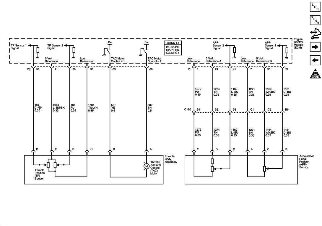
Photo Credit by: bing.com / diagram wiring pedal gmc sensor accelerator throttle position acadia rear mirror p2138 app corvette 2006 anyone help c6 pontiac gm
Gm Accelerator Pedal Position Sensor Wiring Diagram - Micro Wiring
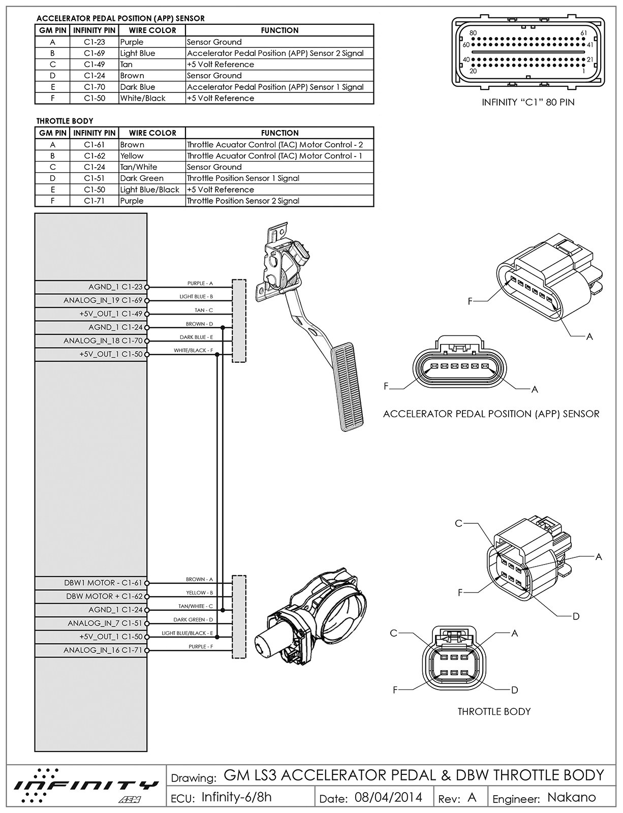
Photo Credit by: bing.com /
Throttle Position Sensor Problem? - RX8Club.com
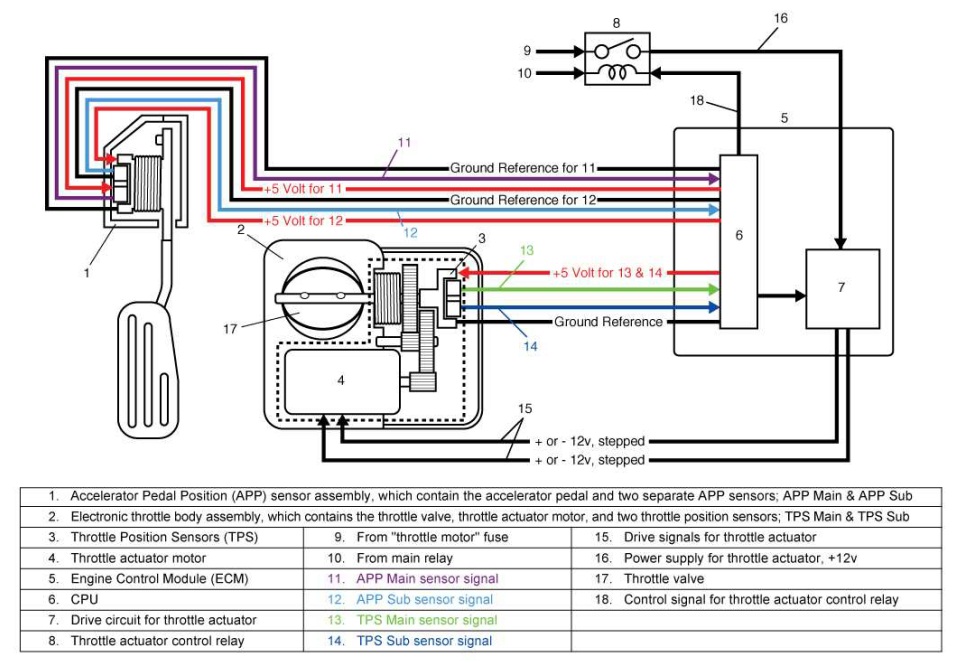
Photo Credit by: bing.com / sensor dbw rx8club denso
6 Pin Accelerator Pedal Position Sensor Wiring Diagram - Rycatriw

Photo Credit by: bing.com /
Accelerator Pedal Position APP Sensor Pigtail GM 6.0L LS2 (05-09 Corve

Photo Credit by: bing.com / pedal accelerator sensor ls2 pigtail 0l
Gm Accelerator Pedal Position Sensor Wiring Diagram - Micro Wiring
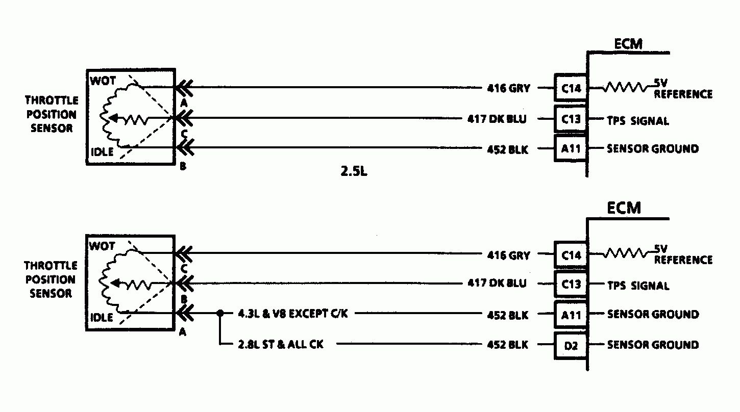
Photo Credit by: bing.com /
Accelerator Pedal Position Sensor Wiring Diagram - Drivenhelios
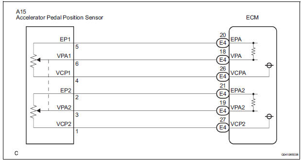
Photo Credit by: bing.com /
Accelerator Pedal Position Sensors (APPS)
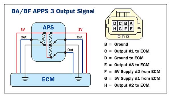
Photo Credit by: bing.com / pedal accelerator position sensor apps throttle dual aps potentiometer type contact output units
Gm Accelerator Pedal Position Sensor Wiring Diagram - Properinspire

Photo Credit by: bing.com /
GM Original Equipment PT2712 Accelerator Pedal Position Sensor

Photo Credit by: bing.com / accelerator gm connector sensor ebay pedal position equipment original


